Archive: September 29, 2025

Electric vs. gas galley installations on boats

The All-Electric Galley: Is It Time to Ditch Propane on Your Boat?

For decades, the rhythmic hiss of a propane stove and the gentle clatter of a gimballed grate have been the quintessential soundtrack to a cruising boat’s galley. Propane has been a reliable, if sometimes fussy, partner for sailors cooking at sea. But a quiet revolution is taking place below decks, powered by advancements in battery technology and high-efficiency appliances. More and more boat owners are asking the question: Is it finally time to cut the gas line and embrace an all-electric galley?

The move from gas to electric is more than just a preference; it’s a fundamental shift in how we manage energy and safety onboard. It’s about trading the periodic anxiety of propane leak checks for the silent, efficient power of induction. This isn’t a simple appliance swap, however. It’s a holistic system upgrade that demands careful planning. Let’s weigh anchor and navigate the real-world considerations of making the switch.

Modern electric galley on a sailboat with induction cooktop and sleek countertops

The Case Against Propane: Why Sailors Are Reconsidering Gas

Before we dive into the allure of electric, it’s important to understand the push factors. Why are seasoned mariners, long accustomed to propane, looking for an alternative? The reasons generally fall into three categories: safety, convenience, and comfort.

The Unspoken Safety Concerns

Let’s be blunt: propane (LPG) is a heavy, highly flammable gas stored under pressure. On a boat, it demands respect and constant vigilance. A proper marine installation includes a dedicated, ABYC-compliant locker that vents overboard, a remote solenoid shut-off valve, and high-quality, chafe-protected lines. Even with a perfect system, the risk of a leak, however small, is always present. Since propane is heavier than air, any escaped gas will sink into the bilge, creating a potential explosion hazard just waiting for a spark. This inherent risk is the number one reason sailors dream of a gas-free boat.

The Convenience Conundrum

Anyone who has cruised internationally knows the frustration of sourcing propane. Bottle fittings and standards vary wildly from country to country, leading to a collection of questionable adapters or the expensive task of acquiring new tanks. It’s a logistical headache that an all-electric system simply eliminates. Furthermore, that dedicated propane locker, while essential for safety, consumes valuable deck or cockpit space that could be repurposed for other gear.

The Heat and Humidity Issue

A often-overlooked byproduct of burning propane is water vapor. Every flame on your stove is releasing moisture directly into your cabin, adding to the ever-present battle against dampness and mildew. On a hot, tropical evening, the ambient heat radiating from a gas stove can also turn the salon into a sauna. An electric galley significantly reduces both of these comfort-killing factors.

The All-Electric Promise: What’s Driving the Change?

The dream of an all-electric galley isn’t new, but until recently, it was impractical for most cruising boats due to power limitations. Two key technological advancements have changed the game entirely.

Induction Cooking: The Heart of the Modern Galley

Induction cooktops are the star players in the electric galley. Unlike traditional electric resistance burners that glow red-hot, induction uses a magnetic field to directly heat the cookware itself. The benefits at sea are massive:

  • Efficiency: Around 85-90% of the energy goes directly into the pot, compared to about 40-50% for gas. This means faster boiling times and less wasted energy.
  • Safety: The cooktop surface stays relatively cool to the touch, drastically reducing the risk of burns. When you remove the pot, the heating stops instantly.
  • Comfort: With almost no waste heat, the galley stays much cooler.
  • Cleaning: A flat, smooth glass surface is infinitely easier to wipe down than a complex gas hob with grates and burners.

The Power Revolution: Lithium (LiFePO4) Batteries

Induction’s high efficiency is great, but it still requires a significant burst of power. This is where older battery technologies, like lead-acid, would falter. The real enabler of the all-electric galley is the rise of Lithium Iron Phosphate (LiFePO4) batteries. They possess the high energy density and, crucially, the high discharge rate capability to power an induction hob and a microwave without damaging the battery bank. They provide the deep, reliable power reservoir needed to make electric cooking a daily reality, not just an occasional luxury when plugged into shore power.

The Reality Check: Planning Your All-Electric Conversion

Tearing out the gas lines is tempting, but a successful conversion requires a systems-based approach. Simply installing an induction cooktop without upgrading the infrastructure is a recipe for frustration.

Step 1: Conduct a Thorough Energy Audit

You cannot guess at your power needs. You must calculate them. An all-electric galley is a power-hungry beast. Start by estimating your cooking usage. A 1500-watt induction burner running for 20 minutes to boil water and cook pasta consumes 500 watt-hours. At 12 volts, that’s roughly 42 amp-hours (Ah) from your battery bank. Do that three times a day, add in a microwave, and you can see how quickly the consumption adds up. For most cruising couples, a LiFePO4 bank of 400Ah is a realistic minimum, with 600-800Ah being a more comfortable target for serious cooking.

Step 2: Plan Your Charging Strategy

A huge battery bank is useless if you can’t refill it. Your charging system must be able to keep up with your new, higher demand. This usually means a multi-pronged approach:

  • Solar: This will be your primary workhorse at anchor. A significant array of 400-800 watts or more, managed by a quality MPPT charge controller, is essential.
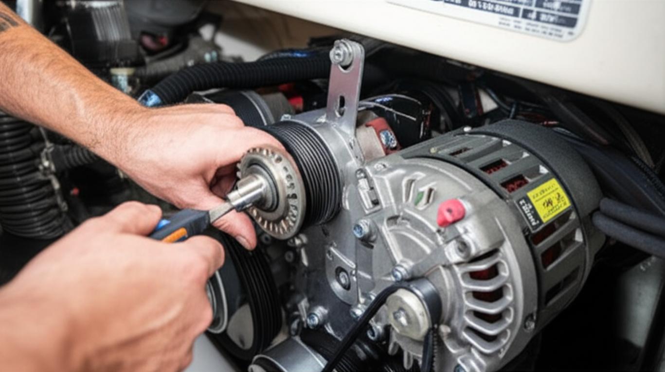
  • Alternator: When motoring, a high-output alternator (120A+) paired with an external regulator that is optimized for lithium charging is key to replenishing the bank quickly.
  • Generator/Shore Power: For extended periods of bad weather or heavy usage, a small generator or the ability to plug into shore power provides a necessary backup.

Step 3: Choose the Right Appliances

With power sorted, you can select your hardware. You’ll need more than just a cooktop.

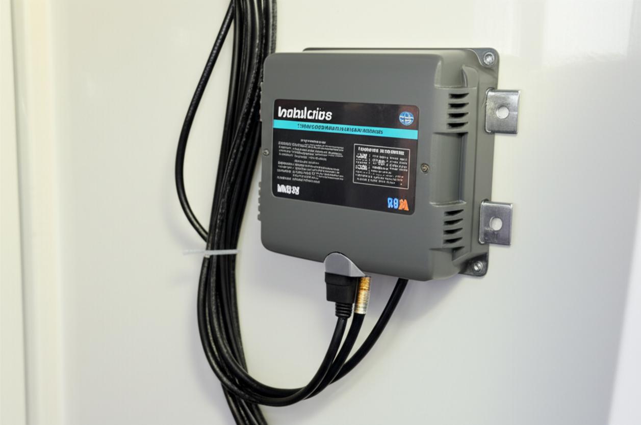
  • Inverter: A high-output, pure sine wave inverter is non-negotiable. This device converts your 12V DC battery power to 120V/230V AC for your appliances. A 2000-watt unit is a bare minimum, but a 3000-watt inverter/charger is a more robust choice that can handle multiple loads.
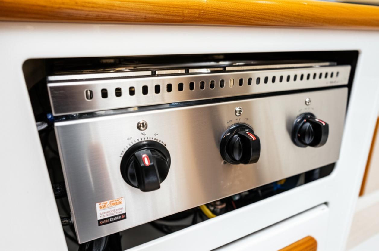
  • Cooktop: Choose a marine-grade or high-quality residential single or double-burner induction unit. Pay attention to its maximum wattage to ensure your inverter can handle it.
  • Other Appliances: A combination microwave/convection oven is a popular, space-efficient choice to replace a traditional gas oven. Electric kettles and toaster ovens also become viable options.

Conclusion: Is the Future of Your Galley Electric?

Making the switch to an all-electric galley is a significant undertaking, both technically and financially. The upfront cost of a substantial LiFePO4 battery bank, a large inverter, solar panels, and new appliances is considerable. It is not a weekend project.

However, the rewards are equally significant. The payoff comes in the form of enhanced safety by removing a volatile gas from your living space, unparalleled convenience with a single fuel source for all your systems, and a cleaner, cooler, and more comfortable cooking environment. For the modern cruiser investing in a robust electrical system, the all-electric galley is no longer a futuristic concept—it’s a logical, safer, and ultimately more enjoyable evolution of life at sea.

Sanitation system check-valves inspection

The Unsung Heroes of Your Head: A Guide to Marine Sanitation Check-Valve Inspection

There are few things on a boat that can sour a perfect day on the water faster than a misbehaving marine head. That faint, unpleasant odor you can’t quite trace, or the slow, creeping return of water into the bowl after you’ve pumped it dry – these are the classic signs that a tiny, yet critical, component in your sanitation system is failing. We’re talking about the check-valve, most famously the ‘joker valve’.

Ignoring this small rubber part is a mistake many a skipper has made, often leading to a messy, foul-smelling, and entirely preventable repair job. This guide isn’t just about fixing a problem; it’s about understanding the system, performing preventative inspections, and ensuring your marine toilet operates reliably, trip after trip. Consider this your definitive playbook for keeping the backflow at bay.

A view of a marine sanitation hose and valve system on a boat, highlighting the complexity of boat plumbing.

Understanding the Enemy: What Are Check-Valves and Why Do They Fail?

At its core, a check-valve is a one-way gate. In a marine sanitation system, its job is to allow waste and water to be pumped out of the toilet bowl and down the discharge line, while preventing anything from flowing back. The most common and crucial of these is the joker valve.

The Joker Valve: Your First Line of Defense

Named for its resemblance to the pointed hat of a court jester, the joker valve is a cone-shaped rubber component with a slit or ‘duckbill’ at the end. When you pump the head, the pressure forces the lips of the valve open to let waste pass through. As soon as the pressure subsides, the natural elasticity of the rubber snaps the lips shut, forming a seal. It’s a simple, brilliant design, but it’s also the system’s weakest link.

The Common Culprits of Failure

Joker valves live in a harsh environment and don’t last forever. Understanding why they fail is the first step to preventing it:

  • Calcification: The combination of urine and saltwater creates a stubborn calcium scale, not unlike concrete. This scale builds up on the joker valve’s lips, preventing them from closing completely. This is, by far, the most common cause of failure.
  • Foreign Objects: A marine head is designed for human waste and marine-grade, rapidly dissolving toilet paper—and nothing else. Conventional toilet paper, paper towels, or sanitary products will not break down and will inevitably get caught in the valve, holding it open.
  • Age & Material Fatigue: Over time, the rubber loses its elasticity. It can become brittle, hard, or simply too weak to form a tight seal. A valve that is several years old is living on borrowed time.
  • Chemical Damage: Harsh chemical cleaners, solvents, or bleach can destroy the rubber, causing it to swell or disintegrate. Only use cleaners specifically formulated for marine sanitation systems.

The Inspection Playbook: A Step-by-Step Guide

Inspecting your joker valve should be on your annual maintenance checklist, or done immediately if you notice symptoms. It’s not the most glamorous job, but with the right preparation, it’s manageable.

Gear Up: Tools and Safety Precautions

Before you open any part of the sanitation system, assemble your gear. Safety and hygiene are paramount.

  • Safety First: Heavy-duty nitrile or rubber gloves are non-negotiable. Safety glasses are a very good idea.
  • Tools: You’ll likely need a set of screwdrivers and perhaps a small wrench or pliers, depending on your head model.
  • Supplies: A bucket, plenty of rags, a small brush, and white vinegar for cleaning.
  • The All-Important Spare: Have a brand-new, correct-model joker valve (and ideally a full service kit) on hand before you start. Never disassemble the head without a replacement ready to go.

Step 1: System Shutdown and Preparation

First, close both the raw water intake and the waste discharge seacocks. Pump the head completely dry. To make the job infinitely more pleasant, flush the system several times with fresh water before you begin disassembly. This will clear the lines of most of the unpleasant contents.

Step 2: Gaining Access to the Valve

The joker valve is typically located in the discharge elbow of the pump assembly. On most manual heads (like the popular Jabsco models), you’ll need to remove the 4 to 6 screws holding the pump assembly to the toilet base. Carefully lift the pump off. Be prepared for a small amount of residual water to spill out—have your rags and bucket ready.

Step 3: The Visual and Tactile Inspection

Once the pump is removed, you can look inside the discharge port and see the joker valve. Carefully pull it out. Now, perform a thorough inspection:

  • Look for Damage: Check for any rips, tears, or pinholes in the rubber.
  • Check for Debris: Look for any scale, hair, or paper caught between the lips. Sometimes, simply cleaning it is enough, but this is rare.
  • The Squeeze Test: A healthy joker valve should be soft and pliable. Squeeze it gently. The lips should spring back together instantly to form a perfect seal. If the material feels stiff, hard, or brittle, it’s time for a replacement.
  • Check for Distortion: If the valve is warped or no longer holds its conical shape, it cannot seal properly.

The “When in Doubt, Swap it Out” Rule

Here’s the most important piece of advice: Joker valves are inexpensive wear items. They cost a fraction of the value of your time and peace of mind. If you’ve gone to the trouble of taking the head apart, and the valve looks even slightly suspect, replace it. It is cheap insurance against having to do this messy job all over again in a few months.

Proactive Maintenance: Preventing Future Failures

The best repair is the one you never have to do. A few simple habits can dramatically extend the life of your sanitation system components.

The Right Diet for Your Head

Be vigilant about what goes into the toilet. Use only marine-grade toilet paper, and use it sparingly. Educate all guests on this rule. A small, polite sign in the head compartment can work wonders.

Regular Descaling: The Vinegar Trick

Calcium scale is your primary enemy. To combat it, flush the system regularly with white vinegar. Once a month, close the intake seacock, pump the bowl dry, and pour in about a pint of white vinegar. Pump it just enough to move it into the hoses and let it sit for several hours (or overnight) before flushing it through. This will dissolve minor scale deposits before they become major blockages.

Keep Spares, Keep Your Sanity

A failed head can ruin a weekend cruise. Every boat owner should have at least two spare joker valves and a complete pump service kit for their specific model stored on board. They take up minimal space and can turn a trip-ending disaster into a 30-minute inconvenience.

Conclusion: Master of Your Marine Domain

The marine sanitation system is often out of sight and out of mind, until it fails. By understanding the critical role of the humble check-valve and adopting a proactive inspection and maintenance schedule, you take control. This isn’t just about avoiding foul odors; it’s about being a competent, self-sufficient skipper who understands their vessel from stem to stern. A little attention to this unglamorous system pays huge dividends in reliability and peace of mind on the water. Fair winds and a trouble-free head!

Check Periodically the Stainless Steel Fittings

More Than a Shine: A Sailor’s Guide to Inspecting Stainless Steel Hardware

There’s nothing quite like the brilliant glint of polished stainless steel against a deep blue sea. It speaks of strength, reliability, and modern seamanship. From the stanchions guarding our decks to the chainplates holding our masts aloft, we place immense trust in these metallic components. But here’s a hard-won piece of sea wisdom: that beautiful shine can be deceiving. Stainless steel, despite its name, is not invincible. In the harsh marine environment, it can and does corrode, crack, and fail—often silently, until it’s too late. A routine inspection of your boat’s hardware is not just a ‘nice-to-do’ task for a quiet Sunday; it’s a fundamental pillar of safe boating.

A collection of marine-grade stainless steel hardware, including turnbuckles and shackles, ready for inspection.

Understanding Marine-Grade Stainless Steel

Before we can properly inspect it, we need to understand what we’re looking at. The term “stainless steel” covers a wide family of alloys, but for marine use, two grades are paramount.

Not All Stainless Is Created Equal: 304 vs. 316

You’ll often encounter Type 304 stainless in general applications. It’s tough and corrosion-resistant in many environments, but it has an Achilles’ heel: chlorides. Saltwater is a chloride-rich soup, and 304 will eventually succumb to pitting and crevice corrosion. For any application on a boat that sees salt spray, and especially for critical components, you need Type 316. The key difference is the addition of a little element called molybdenum. This addition dramatically increases its resistance to chlorides, making 316 the undisputed king for marine hardware. If you’re replacing a fitting, always insist on 316 or its low-carbon variant, 316L.

The Myth of “Stainless”

The magic of stainless steel lies in a microscopic, invisible layer of chromium oxide that forms on its surface when exposed to oxygen. This “passive layer” is what protects the iron in the steel from rusting. The problem is, this protective layer can be damaged. Mechanical scratches, contamination with carbon steel (like from using a steel wire brush), or, most commonly, a lack of oxygen in tight crevices, can break down this barrier and allow corrosion to begin its insidious work.

The Telltale Signs of Trouble: What to Look For

Developing a keen eye for the subtle signs of stainless steel degradation is one of the most valuable skills a skipper can possess. Grab a good flashlight, a magnifying glass, and let’s go on a hunt.

Surface Stains: The Early Warning

Often called “tea staining,” this is a light, reddish-brown surface discoloration. While often cosmetic, you should never ignore it. It can be an early indicator of a poor-quality alloy (perhaps 304 masquerading as 316), contamination, or the beginning of more serious issues. It’s most common in areas that don’t get a regular freshwater rinse. A good polish with a specialized cleaner can often remove it, but note the location and keep a close eye on it.

Crevice Corrosion: The Hidden Danger

This is one of the most common and dangerous forms of failure. It occurs in oxygen-starved environments, such as under the head of a bolt, beneath a washer, between the threads of a turnbuckle, or where a chainplate passes through the deck. Water gets trapped, the oxygen is consumed, and the passive layer breaks down, creating an acidic environment that aggressively attacks the steel. The telltale sign is a weeping rust stain emanating from the joint. If you see this, that fitting needs to be disassembled, inspected, and likely replaced immediately.

Pitting: Small Holes, Big Problems

Pitting is localized corrosion that creates small, deep cavities in the steel. A few tiny pits on a cleat might not be a major concern, but on a high-load component like a rigging terminal or a prop shaft, they can act as stress risers, becoming the starting point for a stress crack. Pitting indicates that the passive layer has been compromised in specific spots, often due to microscopic imperfections in the metal or prolonged exposure to stagnant saltwater.

Stress Corrosion Cracking (SCC) and Fatigue: The Silent Catastrophe

This is the one that keeps riggers up at night. SCC is the formation of microscopic cracks in metal that is under tensile stress in a corrosive environment—a perfect description of a boat’s rigging. These cracks can propagate with no obvious outward sign of corrosion, leading to sudden, catastrophic failure. You need a magnifying glass to even have a chance of spotting them. Look for them in high-stress areas: the bends of chainplates, around swage fittings, and on toggle pins. If you suspect SCC on a critical component, the only safe course of action is replacement or professional non-destructive testing, such as dye penetrant inspection.

A Practical Inspection Checklist

Make this a part of your regular maintenance schedule—at least twice a season, and before any major passage.

Deck Hardware & Rigging

  • Stanchions and Lifelines: Vigorously wiggle each stanchion. Check the bases for fine, hair-like cracks radiating from the mounting bolts. Inspect lifeline terminals (swaged or mechanical) for any signs of cracking or corrosion.
  • Chainplates: This is ground zero for potential failure. On deck, check the sealant for any breaks. Look for fine cracks where the plate bends. Below deck, use a mirror and flashlight to inspect the entire length. Any weeping rust stains are a major red flag that crevice corrosion is at work where you can’t see it.
  • Turnbuckles: At least annually, slacken your rigging and unwind every turnbuckle. Clean the threads thoroughly and inspect them for corrosion and galling (where the threads bind and tear). Lubricate with a suitable anti-seize compound before re-tuning.
  • Shackles, Blocks, and Toggles: Check shackles for any signs of elongation or deformation—a sign they have been overloaded. Ensure clevis pins are straight and cotter pins are sound. The sheaves in blocks should turn freely.

Hull and Systems

  • Thru-Hulls and Seacocks: While less common in stainless, inspect any such fittings for pitting and crevice corrosion, especially around the flange.
  • Prop Shaft and Rudder Stock: During haul-out, carefully inspect shafts for any pitting or signs of galvanic corrosion, especially near the prop or any bearings.

Prevention: The Best Maintenance Strategy

An ounce of prevention is worth a ton of cure, especially at sea.

  • Freshwater Rinse: The simplest and most effective preventative measure. A thorough freshwater washdown after every sail removes the corrosive salt deposits.
  • Clean and Passivate: Regularly clean your stainless with a proper marine-grade cleaner (never use steel wool or carbon steel brushes!). To restore the protective layer, you can use a mild acid like oxalic acid, which will remove surface impurities and allow the chromium oxide layer to reform perfectly.
  • Proper Bedding: Ensure all deck hardware is bedded with a high-quality marine sealant. This prevents water intrusion, which is the root cause of crevice corrosion. Dig out and replace any old, cracked sealant.

Conclusion: Trust, but Verify

Your boat’s stainless steel hardware is the silent workhorse that keeps your rig standing and your crew safe. It withstands incredible forces in a relentlessly corrosive environment. But it requires your attention and your diligence. Don’t be lulled into a false sense of security by a pretty shine. Get out there, look closely, and learn the language of your hardware. A few hours of careful inspection can be the difference between a safe passage and a catastrophic failure. Trust your hardware, but always, always verify.

Marine Air Conditioner Installation

Beat the Heat: A Comprehensive Guide to Installing Marine Air Conditioning

There are few things less enjoyable than being trapped in a sweltering, humid cabin after a perfect day on the water. The air gets thick, cushions feel damp, and sleeping becomes a sticky, restless affair. This is where a marine air conditioning system transforms from a luxury into a near necessity. It’s not just about comfort; it’s about protecting your boat’s interior from mildew and making your time aboard truly relaxing. But installing one isn’t as simple as plugging in a window unit from a hardware store. Marine AC installation is a serious project that demands careful planning and a deep respect for the unique challenges of the marine environment.

As a marine professional who has seen countless installations—both good and bad—I’ve created this guide to walk you through the entire process. We’ll cover everything from choosing the right system to the critical details that separate a reliable, efficient installation from a future headache.

Why You Can’t Just Use a Household AC Unit

Before we dive in, let’s clear up a common question: “Can I just install a cheap portable or window AC unit on my boat?” The answer is an emphatic no. A boat is a harsh environment, and marine-grade equipment is built to survive it. Here’s why a standard unit will fail:

  • Corrosion: The salty, humid air will rapidly corrode the coils and electronics of a residential unit. Marine systems use specialized materials like cupronickel for condenser coils and stainless steel components to resist saltwater corrosion.
  • Cooling Method: Marine ACs don’t use a fan to cool the condenser like a home unit. They use a continuous flow of raw seawater, which is a far more efficient method of heat exchange. This requires a thru-hull, pump, and plumbing that household units lack.
  • Condensate Management: Boats move, heel, and rock. Marine AC units are designed with deep, robust condensate pans and drains to manage the water they pull from the air, preventing spills that can lead to bilge water, mold, and rot.
  • Durability: Everything on a boat gets shaken and slammed around. Marine systems are built to withstand the constant vibration and shock of life at sea.

Choosing Your Weapon: Types of Marine AC Systems

The right system for your vessel depends on its size, layout, and your budget. The three main types are self-contained, split-gas, and chilled water systems.

Self-Contained Units

This is the most common type for boats under 40-45 feet. The entire system—compressor, condenser, and evaporator—is housed in a single chassis. You install the unit in the living space (often under a settee or in a locker) and run ductwork to one or more vents.

  • Pros: Relatively simple to install, cost-effective, and compact. They are the go-to choice for most DIY installations.
  • Cons: The compressor is in your living space, so they can be noisier than other options. They are also less efficient for cooling multiple, separate cabins.

Split-Gas Systems

Similar to central air in a home, these systems separate the components. The noisy condenser/compressor unit is installed in a mechanical space like the engine room, while one or more quiet air handlers are placed in the cabins. Refrigerant lines connect the two parts.

  • Pros: Much quieter in-cabin operation and offer great flexibility for cooling multiple areas.
  • Cons: Installation is significantly more complex and expensive. It requires handling refrigerant, which legally requires an EPA-certified technician in many places. This is rarely a DIY job.

Chilled Water Systems

Found on larger yachts and commercial vessels, these are the pinnacle of marine climate control. A large chiller in the engine room cools a closed loop of fresh water (mixed with glycol), which is then pumped throughout the vessel to individual air handlers in each cabin. These systems can also provide reverse-cycle heating very efficiently.

  • Pros: Extremely efficient, quiet, and scalable for any size vessel.
  • Cons: By far the most complex and expensive to install and maintain. Strictly a job for specialized professionals.

The Installation Blueprint: Planning is Everything

A successful installation is 90% planning. Rushing this stage is a recipe for disaster. Here’s your pre-installation checklist.

1. Sizing the Unit: The BTU Game

Choosing the right capacity, measured in BTUs (British Thermal Units), is critical. Too small, and it will run constantly without cooling the boat. Too large, and it will short-cycle, failing to dehumidify the air properly and causing premature wear. A rough rule of thumb is 14-16 BTUs per cubic foot of cabin space. However, you must adjust for:

  • Windows and Hatches: Large, unshaded windows add a significant heat load.
  • Sun Exposure: A boat with a dark hull or deck will get much hotter.
  • Location: A boat in the tropics needs more cooling power than one in New England.
  • Insulation: Well-insulated hulls require less BTU capacity.

Consult the manufacturer’s guidelines carefully. When in doubt, it’s better to be slightly undersized than oversized.

2. Location, Location, Location

Where you place the components is just as important as the unit itself.

  • The Main Unit (Self-Contained): Find a spot that is low in the boat, central to the area you want to cool, and has space for ducting. Under a berth or settee is common. Crucially, ensure you have easy access for maintenance and a clear path for the condensate drain.
  • Return Air: The unit needs to draw in warm cabin air. This return vent should be as large as possible and unobstructed. Never install the unit in an engine room where it could pull in fumes.
  • Supply Vents: Position your cool air supply vents high in the cabin, as cool air sinks. Aim for a circular airflow pattern, with the supply and return vents at opposite ends of the space.

3. The Seawater Circuit: The Heart of the System

This is the most critical part of the installation. A failure here can sink your boat.

  • Thru-Hull & Seacock: The water intake must be a dedicated thru-hull fitting with a proper marine seacock. It should be located where it will remain submerged even when the boat is heeling or planning.
  • Sea Strainer: A sea strainer is non-negotiable. It must be installed between the seacock and the pump to protect the pump and condenser coils from debris. Mount it above the waterline for easy cleaning.
  • Pump: The circulation pump must be mounted below the waterline to ensure it stays primed.
  • Hoses & Clamps: Use high-quality reinforced marine hose and double-clamp all connections below the waterline with marine-grade stainless steel clamps. Create a vented loop in the discharge line if the outlet is near the waterline to prevent siphoning.

4. Electrical Power: Don’t Skimp on Amps

Marine air conditioners are power-hungry, especially on startup. You need a robust AC electrical system.

  • Power Source: You’ll need sufficient shore power (typically a 30A service) or a properly sized generator to run the AC away from the dock.
  • Wiring: The unit must be on its own dedicated circuit with the correct size breaker. Use marine-grade tinned wire and follow all ABYC standards for wiring practices.

The Big Question: DIY or Hire a Pro?

Installing a self-contained marine AC system can be a rewarding project for a skilled and confident boat owner. If you are comfortable with fiberglass work (for the thru-hull), 120V AC electrical systems, and plumbing, you can likely tackle the job.

However, you should hire a certified marine technician if:

  • You have any doubts about cutting a hole in your hull.
  • You are not 100% confident in your AC electrical skills.
  • You’re installing a split-gas or chilled water system.
  • You want the peace of mind and warranty that comes with a professional installation.

Conclusion: A Worthwhile Investment in Comfort

Installing a marine air conditioning system is a significant upgrade that will fundamentally change how you use and enjoy your boat. It extends your boating season, preserves your interior, and provides an incredible quality-of-life improvement. While the installation process is involved and requires meticulous attention to detail, the reward is a cool, dry, and comfortable sanctuary on the water. Plan carefully, respect the systems you’re working with, and don’t hesitate to call in a professional if you’re out of your depth. Your future, well-rested self will thank you for it.

How to Change Belts in a Marine Alternator

The Unsung Hero in Your Engine Room: The Alternator Belt

There’s a sound every seasoned mariner knows and dreads: a high-pitched, persistent squeal from the engine room, especially when the throttle is pushed forward. It’s the desperate cry of a slipping alternator belt. This humble loop of reinforced rubber is one of the most critical, yet often overlooked, components of your vessel’s powerplant. It’s the mechanical link that turns your engine’s raw power into the electrical lifeblood that charges your batteries, runs your navigation gear, and keeps your lights on. When it fails, you’re not just inconvenienced; you’re dead in the water, electrically speaking. Understanding how to inspect, replace, and properly tension this belt—a process known in Spanish-speaking ports as ‘cambio de correas’—is a fundamental skill for any self-reliant boat owner.

A marine diesel engine with a focus on the alternator and its belts, illustrating a key maintenance task for boat owners.

Why This ‘Simple’ Belt Demands Your Respect

On land, a failed alternator belt might mean a call to a tow truck. At sea, the stakes are exponentially higher. This belt harnesses the rotation of the engine’s crankshaft and spins the alternator’s pulley. The alternator, in turn, generates the DC current needed to replenish your battery banks. Without it, you’re running solely on battery power, a finite resource that will dwindle with every running light, chartplotter, or VHF transmission. On many marine engines, this same belt also drives the raw water pump, which is essential for engine cooling. In that scenario, a snapped belt means no charging and a rapidly overheating engine—a true emergency. The harsh marine environment of salt, humidity, heat, and constant vibration is hell on rubber components, making regular inspection not just good practice, but a critical safety procedure.

Reading the Signs: When to Perform a ‘Cambio de Correas’

Your belt will almost always give you warning signs before it fails catastrophically. You just need to know what to look and listen for.

Visual Inspection: Your First Line of Defense

With the engine off and cool, run your fingers (and a good flashlight) over the belt. You’re looking for:

  • Cracks: Any visible fissures or cracks, especially on the ribbed or V-groove side, are a clear sign the rubber is drying out and ready to fail.
  • Glazing: A shiny, polished surface on the sides of the belt indicates it has been slipping. This hardens the rubber, reduces grip, and is a precursor to squealing and failure.
  • Fraying or Delamination: If the edges are frayed or the layers of the belt are starting to separate, its structural integrity is compromised. Replace it immediately.
  • Belt Dust: An excessive amount of black, rubbery dust around the alternator and pulleys is a tell-tale sign of rapid wear, often due to misalignment or improper tension.

Audible and Performance Warnings

Sometimes you’ll hear the problem before you see it:

  • Squealing: The classic symptom. It’s most common on startup or when a heavy electrical load (like a windlass) is applied, causing the alternator to work harder and the belt to slip.
  • Inconsistent Voltage: If you notice your onboard voltmeter flickering or reading lower than usual (typically should be 13.8V-14.4V when charging), a slipping belt could be the culprit.

Gearing Up: Tools and Parts for the Job

Performing a belt change underway is much easier if you have the right gear ready. Don’t wait until you’re in a rolling sea to discover you’re missing a 14mm socket.

Your Essential Toolkit

  • Socket Set and Wrenches: A good metric and/or SAE set is essential. You’ll typically need a few specific sizes for the alternator’s pivot and tensioning bolts.
  • Pry Bar or Large Screwdriver: For safely applying leverage to tension the new belt.
  • Flashlight or Headlamp: Engine rooms are notoriously dark.
  • Rags: For cleaning pulleys and hands.
  • Belt Tension Gauge (Optional): For those who prefer precision, this tool takes the guesswork out of tensioning.

Choosing the Right Belt (and a Spare!)

Belts are not one-size-fits-all. You need the exact part number for your engine. This can usually be found on the old belt itself, in your engine’s service manual, or by contacting the manufacturer. The golden rule of cruising: carry at least two spares. Store them in a sealed plastic bag in a cool, dark, and dry place to protect them from UV and ozone degradation.

The Step-by-Step Guide to Changing Your Alternator Belt

With your tools and new belt in hand, you’re ready to get to work. It’s a straightforward process that builds confidence with every turn of the wrench.

  1. Safety First: Ensure the engine is completely off and cool to the touch. Disconnect the negative terminal from your start battery to prevent any chance of an accidental start.
  2. Document the Path: Before you touch anything, take a clear photo of the belt’s routing. This is especially crucial for complex serpentine belts that weave around multiple pulleys.
  3. Loosen for Slack: Identify the alternator’s bolts. There will be a main pivot bolt and an adjusting bolt, often on a slotted bracket. Loosen the adjusting bolt first, then slightly loosen the pivot bolt. You don’t need to remove them completely.
  4. Relieve Tension & Remove: With the bolts loose, push the alternator towards the engine block. This will create slack in the belt, allowing you to easily slip it off the pulleys.
  5. Inspect and Clean Pulleys: This is a critical, often-skipped step. With the belt off, spin each pulley by hand. They should spin smoothly and silently. Check the V-grooves for rust, debris, or embedded rubber. Clean them thoroughly with a wire brush and a rag. A dirty or damaged pulley will shred a new belt in short order.
  6. Install the New Belt: Referring to your photo, carefully route the new belt around the pulleys. Make sure the ribs are properly seated in the grooves.
  7. Tensioning – The Critical Art: This is the most important step. Too loose, and the belt will slip and fail to charge. Too tight, and you’ll put immense strain on the bearings of your alternator and raw water pump, leading to expensive failures.
    • The Rule of Thumb: Find the longest span of the belt between two pulleys. With firm thumb pressure, you should be able to deflect the belt about 1/2 inch (1.3 cm).
    • Applying Tension: Use your pry bar to gently lever the alternator away from the engine. Find a solid casting point on the alternator body to pry against—never pry on the plastic fan, cooling fins, or the rear casing. While holding tension, tighten the adjusting bolt first to lock it in place, then fully tighten the pivot bolt.
  8. Final Checks: Double-check the tension. Reconnect the battery. Start the engine and let it run for a minute. Listen for any squeals and observe the belt to ensure it’s tracking correctly. Check your voltmeter to confirm a healthy charging voltage. Shut down, let everything cool, and re-check the tension one last time. New belts have an initial stretch, so a slight re-tension is often necessary.

A Seaman’s Final Word

Mastering the ‘cambio de correas’ is more than just a maintenance task; it’s an act of self-sufficiency. It transforms a potential trip-ending disaster into a manageable, 30-minute inconvenience. By regularly inspecting your belts, carrying the correct spares, and knowing the replacement procedure by heart, you are taking direct command of your vessel’s reliability and your own safety at sea. It’s one of the most valuable skills you can have in your mariner’s toolkit, providing peace of mind that is worth far more than the cost of a few spare belts.

Instalación de AIS transponder Clase B

Visibility is Safety: Why a Class B AIS Transponder is Non-Negotiable

There are few things more unsettling at sea than limited visibility. Whether it’s the dead of night, a rolling fog bank, or torrential rain, the moment your world shrinks to just a few boat lengths is the moment you truly appreciate modern electronics. For years, radar was the gold standard, and it’s still a fantastic tool. But the game changed with the widespread adoption of the Automatic Identification System (AIS). While a simple AIS receiver is good, a Class B transponder is a revolutionary leap in situational awareness and safety for recreational vessels. It doesn’t just let you see others; it lets everyone see you.

Installing an AIS transponder isn’t black magic, but it demands more care than wiring a new cabin light. A sloppy installation can lead to poor performance or, worse, a false sense of security. Having fitted dozens of these units on everything from weekend cruisers to blue-water voyagers, I’ve seen the common pitfalls and the best practices. This guide is your roadmap to a professional-grade installation, ensuring your AIS works flawlessly when you need it most.

Before You Unbox: The Pre-Installation Checklist

Excitement to get new gear installed is understandable, but a little prep work saves major headaches down the line. Before you drill a single hole, let’s get our ducks in a row.

1. Obtain Your MMSI Number

This is non-negotiable. An AIS transponder is useless without a Maritime Mobile Service Identity (MMSI) number. This unique nine-digit code is your vessel’s digital fingerprint. It’s programmed into your AIS and your DSC-equipped VHF radio. When you transmit, this number identifies you to other vessels and shore stations. In the US, you can get an MMSI from the FCC (required for international voyages) or from organizations like BoatUS for domestic use. Whatever your method, have this number in hand before you start. Crucial tip: Most AIS units only allow you to program the MMSI once. A mistake could mean sending the unit back to the manufacturer. Double, then triple-check the number before entering it.

2. Choose Your Transponder: CSTDMA vs. SOTDMA

Not all Class B transponders are created equal. The newer standard is Class B SOTDMA (Self-Organizing Time Division Multiple Access). These units use the same technology as Class A transponders found on commercial ships, offering a higher transmission power (5 watts vs. 2 watts) and a more frequent, intelligent reporting rate. While the older CSTDMA (Carrier-Sense Time Division Multiple Access) units are still effective and often cheaper, if you’re buying new, I strongly recommend a SOTDMA model. The performance boost, especially in high-traffic areas, is significant.

3. Plan Your Component Layout

Walk around your boat and physically identify where each component will live. You’ll have:

  • The AIS Transponder Unit: Needs a dry, well-ventilated location, reasonably close to your helm or nav station for data connections and not too far from a power source. Keep it away from sources of major interference like engine alternators or radar magnetrons.
  • VHF/AIS Antenna: The higher the better. We’ll dive deep into this next.
  • GPS Antenna: Most modern AIS transponders come with their own dedicated GPS antenna. This needs a clear view of the sky, away from radar arches or booms that could block its signal.
  • Power and Data Wires: Trace the path these will take. Avoid running them parallel to high-current cables to prevent interference.

The Antenna System: The Most Critical Component

Your AIS is a radio. Its performance is directly tied to its antenna. A top-of-the-line transponder with a poor antenna setup is a waste of money. You have two primary options here, each with its own merits.

Option 1: The Dedicated VHF/AIS Antenna (The Gold Standard)

This is, without a doubt, the best method. Installing a separate VHF antenna just for your AIS provides the cleanest signal and maximum range for both transmitting and receiving.

  • Placement is Key: Mount this antenna as high as possible, typically on a spreader, radar arch, or its own pole at the stern. The goal is line-of-sight communication.
  • Separation Matters: To avoid interference, ensure at least 3-4 feet of separation between your AIS antenna and your primary VHF radio antenna. Don’t mount them side-by-side on the same masthead bracket.
  • Cable Quality: Don’t skimp on the coaxial cable. For runs over 20 feet, use high-quality, low-loss RG-213 or LMR-400 cable, not the thinner RG-58 often bundled with antennas. Every decibel of signal loss in the cable reduces your effective range.

Option 2: The VHF Antenna Splitter (The Practical Compromise)

For many sailors, especially those with single-masted vessels, adding another antenna at the masthead is impractical. This is where an AIS-rated VHF antenna splitter comes in. This device allows your AIS and your VHF radio to share a single antenna. However, be aware of the trade-offs:

  • Zero-Loss vs. Passive: Only use a high-quality, “zero-loss” or “amplified” splitter. These devices electronically manage the signal traffic and amplify it slightly to overcome any inherent loss. Cheap, passive splitters will degrade the performance of both your AIS and VHF radio.
  • Priority to VHF: All good splitters give priority to your VHF radio. If you transmit on the radio, the AIS is momentarily disconnected. This is a crucial safety feature for voice communications.
  • Single Point of Failure: The downside is that if your single antenna or its cable fails, you lose both your VHF and your AIS. A dedicated system offers redundancy.

Connecting the Dots: Power and Data Integration

Powering Your Unit

Your AIS is a critical piece of safety equipment; give it a clean, reliable power source. Connect it to a dedicated circuit breaker on your DC panel. Use properly sized marine-grade wire to minimize voltage drop, and ensure the connection is protected with the inline fuse supplied by the manufacturer. A stable power supply is essential for consistent transmission.

Integrating with Your Chartplotter (NMEA 2000 vs. NMEA 0183)

Seeing AIS targets overlaid on your electronic charts is where the magic happens. How you connect your AIS to your Multi-Function Display (MFD) or chartplotter depends on your boat’s existing network.

  • NMEA 2000 (N2K): This is the modern, plug-and-play standard. If you have an N2K backbone, installation is as simple as connecting the AIS to the network with a T-connector. The AIS will draw power from the network (check power budget) and share data with all other compatible devices.
  • NMEA 0183: This is the older, serial-based protocol. It involves wiring specific “talker” and “listener” wires. Your AIS will have NMEA 0183 output wires (e.g., TX+, TX-) that need to be connected to the NMEA 0183 input port on your chartplotter (e.g., RX+, RX-). Pay close attention to the wiring diagrams for both devices, as it’s easy to mix them up. The AIS also needs to receive GPS data, so you’ll also connect the chartplotter’s NMEA 0183 output to the AIS’s input. Ensure the baud rate is set correctly (typically 38,400 for AIS).

The Final Steps: Programming and Testing

With everything physically installed, it’s time to bring your system to life. You’ll need to connect your transponder to a computer via USB or WiFi (depending on the model) to run the manufacturer’s configuration software. This is where you’ll enter that all-important MMSI number, your vessel’s name, call sign, length, beam, and vessel type. Be meticulous here; this is the information other ships will see.

Once programmed, it’s time to test. Power everything up. The AIS unit will have status indicator lights that should confirm it has a GPS lock and is transmitting correctly. On your chartplotter, you should start seeing AIS targets pop up. To confirm you are being seen, you can use a website like MarineTraffic or VesselFinder. Search for your boat’s name or MMSI. Be patient—it can take anywhere from a few minutes to an hour for your signal to be picked up by a shore station and appear online. The ultimate test? Call a buddy on a nearby boat and ask if they see you on their screen.

Conclusion: A Worthwhile Investment in Peace of Mind

Installing a Class B AIS transponder is one of the most significant safety upgrades you can make to your vessel. It turns your boat from a passive blip on a radar screen into an active, identified participant in the maritime environment. By taking the time to plan the installation, paying special attention to the antenna system, and ensuring clean power and data connections, you’re not just adding another gadget—you’re investing in peace of mind. Out on the water, especially when conditions turn sour, that’s a currency beyond compare.

Keeping Your Deck Bristol Fashion: A Sailor’s Guide to Repairing Minor Cracks

We’ve all seen them. Those fine, web-like lines spreading from a stanchion base or a tiny, singular crack appearing near a cleat. For a boat owner, discovering a new crack in the deck’s gelcoat can bring a familiar, sinking feeling. While it’s easy to dismiss them as simple cosmetic blemishes, these small fissures can be the proverbial chink in your vessel’s armor. They are not just unsightly; they are potential gateways for water intrusion, which can lead to much bigger, more expensive problems down the line, such as core delamination. The good news is that repairing minor gelcoat cracks is a highly achievable DIY project. With a little patience, the right materials, and a methodical approach, you can restore your deck’s integrity and appearance, keeping your boat in ‘Bristol fashion’.

Understanding the Enemy: What Causes Deck Cracks?

Before we dive into the repair, it’s helpful to understand what you’re dealing with. Gelcoat is the smooth, glossy outer layer of your fiberglass deck. Think of it as a very thick, durable, and somewhat brittle paint. Cracks typically fall into two categories:

* Crazing (or Spider Cracks): These are very fine, shallow cracks that often spread out in a web-like pattern. They are usually caused by the gelcoat becoming brittle from age and UV exposure, or from minor flexing of the deck beneath it. While alarming in appearance, they are typically cosmetic. * Stress Cracks: These are often single, deeper cracks that radiate from a point of high stress. Common culprits include overtightened hardware (like cleats, winches, or stanchions), a minor impact, or significant flexing in a specific area of the deck. These warrant more immediate attention as they are more likely to let water in.

It’s crucial to distinguish these from major structural cracks, which are often deep, wide, and may show signs of movement. If you suspect a crack is structural, or if the area around it sounds hollow when you tap it (a sign of delamination), it’s time to put down the tools and consult a professional marine surveyor or fiberglass expert.

The Essential Toolkit: Gathering Your Supplies

A professional-looking repair is all about preparation, and that includes having the right tools and materials on hand before you start. You don’t want to be scrambling for supplies once you’ve mixed your epoxy.

For Preparation: * Degreaser/Solvent: Acetone is the go-to for cleaning and de-waxing the area. * Rotary Tool (like a Dremel): With a small V-shaped or ball-shaped grinding bit. This is the best way to open up the crack. * Alternative to Rotary Tool: A ‘church key’ can opener or a dedicated crack-opening tool works well for manually scraping open the crack. * Masking Tape: High-quality painter’s tape to isolate your work area. * Safety Gear: Nitrile gloves, safety glasses, and a dust mask or respirator are non-negotiable.

For the Repair: * Gelcoat Paste: This is thicker than regular gelcoat and is designed to fill cracks and gouges without running. It’s essential to get a close color match. Many suppliers offer color-matching kits, or you can buy a neutral base and add tinting pigments. * Catalyst (MEKP): Methyl Ethyl Ketone Peroxide is what makes the gelcoat harden. Handle with extreme care. * Mixing Sticks and Cups: For blending the paste and catalyst. * Plastic Spreader or Putty Knife: For applying the paste.

For Finishing: * Release Agent: Either a clear PVA mold release film, or simply a piece of wax paper or heavy-duty plastic taped tightly over the repair. * Sanding Block: Crucial for achieving a flat, even surface. * Wet/Dry Sandpaper: A range of grits is essential. Start with around 220 or 320, and progress through 400, 600, 800, and up to 1200 or 1500 for a perfect finish. * Polishing Compound: A marine-grade rubbing compound followed by a finer finishing polish. * Buffer/Polisher (Optional): Can be done by hand, but a machine saves time and effort. * High-Quality Marine Wax: To protect your finished repair.

[Image: A well-organized toolkit for gelcoat repair laid out on a clean non-slip boat deck, showing a Dremel, gelcoat paste, sandpaper, and safety glasses.]

The Step-by-Step Repair Process

With your toolkit ready, it’s time to get to work. Choose a calm, dry day with moderate temperatures—ideally out of direct, hot sunlight.

Step 1: Clean and Prepare the Area Thoroughly clean the crack and the surrounding area with acetone on a clean rag. This removes wax, dirt, and oils that could prevent the new gelcoat from bonding properly.

Step 2: Open the Crack (The ‘V-Groove’) This is the most crucial and often most intimidating step. You must widen the crack to give the new gelcoat paste enough surface area to grab onto. Using your Dremel on a low speed or your manual tool, carefully grind or scrape along the crack, creating a V-shaped groove. The bottom of the ‘V’ should be at the bottom of the crack. This ensures you’ve removed all the fractured, weak gelcoat and have a solid base for your repair.

Step 3: Mask Off the Area Use masking tape to create a clean border around the V-groove you just made. This will protect the surrounding undamaged gelcoat from paste and sanding scratches.

Step 4: Mix and Tint the Gelcoat Paste Follow the manufacturer’s instructions precisely. Scoop a small amount of gelcoat paste into a mixing cup. If you need to tint it, add the pigment drop by drop and mix thoroughly until you have a perfect match. Once you’re happy with the color, add the correct amount of MEKP catalyst and mix again. Work quickly and in small batches; once the catalyst is added, you have a limited working time before it starts to harden.

Step 5: Apply the Paste Using a plastic spreader, force the paste firmly into the V-groove. The goal is to eliminate any air bubbles. Overfill the groove slightly, leaving the paste proud of the surrounding deck. This is important because the material will shrink a tiny bit as it cures, and you’ll need the excess material to sand down to a flush surface.

Step 6: Seal the Repair to Cure Standard gelcoat will not fully harden if exposed to air. You must seal it. The easiest method is to lay a piece of wax paper or clear plastic over the wet paste and smooth it out. Alternatively, you can spray it with a PVA mold release agent. This creates an air barrier, allowing a full, hard cure.

Step 7: The Art of Sanding Once the gelcoat is rock-hard (allow at least 24 hours), it’s time for the finishing work. Remove your air barrier and tape. Begin wet sanding with your coarsest grit (e.g., 320) wrapped around a sanding block. Use plenty of water and light, even pressure. Your goal is to sand the excess filler down until it is perfectly flush with the surrounding deck. You’ll know it’s flush when the sanding pattern is uniform across the repair and the adjacent original gelcoat. Progressively work your way up through the finer grits (400, 600, 800, 1200), with each new grit removing the scratches from the previous one. The surface should feel silky smooth by the end.

Step 8: Compound and Polish With the sanding complete, the repair area will look dull. This is where the magic happens. Apply a small amount of rubbing compound and, using a clean cloth or a buffer, work the area until the shine starts to return. Wipe it clean and follow up with a finer finishing polish to bring back that deep, glossy finish that matches the rest of your deck.

Step 9: Wax and Protect Finally, apply a coat of high-quality marine wax over the repaired area to protect it from UV rays and the elements. Step back and admire your work—a virtually invisible repair that has restored both the look and the integrity of your deck.

Conclusion

Repairing minor deck cracks is more than just a maintenance chore; it’s an investment in your boat’s longevity and value. It’s a skill that builds confidence and deepens the connection between a sailor and their vessel. By taking a careful, step-by-step approach, you can eliminate those unsightly blemishes and ensure your deck remains strong, watertight, and ready for whatever the sea throws its way. Fair winds and flawless decks!

Power Up Your Peace of Mind: A Sailor’s Guide to Installing a Smart Battery Charger

There are few sounds more disheartening to a sailor than the weak, defeated groan of a starter motor or the dim flicker of cabin lights. Our batteries are the heart of our vessel’s comfort and safety systems, and keeping them healthy is non-negotiable. For years, many of us relied on old, buzzing ferro-resonant chargers that did little more than dump raw power into our expensive battery banks. Thankfully, technology has given us a far superior solution: the multi-stage smart battery charger. Upgrading to one of these units is one of the most significant improvements you can make to your boat’s electrical system, extending battery life and providing reliable power when you need it most. This guide will walk you through the why, the what, and the how of installing one, turning a potentially intimidating project into a manageable and rewarding one.

Why Go Smart? The Demise of the ‘Dumb’ Charger

Before we grab our tools, it’s crucial to understand why this upgrade is so important. Traditional, or ‘dumb’, chargers operate on a simple principle: they supply a constant voltage. While this gets the job done, it’s a brute-force approach that is terrible for battery longevity. They often overcharge batteries, boiling off electrolyte in flooded lead-acid types and permanently damaging sealed AGM or Gel cells. They have no way of sensing the battery’s actual state of charge or temperature, leading to inefficient and harmful charging cycles.

A smart charger, on the other hand, is like having a battery doctor onboard. It uses a microprocessor to monitor the battery bank and delivers a tailored, multi-stage charging profile:

* Bulk Stage: Pushes the maximum safe amperage into the batteries to bring them up to about 80% capacity quickly. * Absorption Stage: The voltage is held constant while the amperage gradually tapers off. This ‘tops off’ the final 20% of the charge without over-pressurizing the cells. * Float Stage: Once fully charged, the charger drops to a lower maintenance voltage, providing just enough power to offset any self-discharge. This keeps the batteries at 100% without the damaging effects of a constant high charge. * Equalization (for lead-acid): Some advanced chargers have an equalization mode, a controlled overcharge that helps de-sulfate the battery plates and prolongs the life of flooded lead-acid banks.

The result? Faster, more efficient charging, significantly longer battery life, and the confidence that your power system is being managed optimally.

Choosing Your New First Mate: Selecting the Right Smart Charger

Not all smart chargers are created equal. Here’s what to look for:

* Amperage Output: A good rule of thumb is to have a charger with an output of 10% to 25% of your total house bank’s amp-hour (Ah) capacity. For a 400Ah bank, a charger between 40 and 60 amps is a great choice. A larger charger will recharge faster, but don’t go overboard, as excessively high amperage can also damage batteries. Battery Chemistry Compatibility: This is critical. Your charger must* have settings that match your battery type: Flooded Lead-Acid, AGM, Gel, or Lithium (LiFePO4). Each has a unique voltage requirement for its charging stages. Using the wrong profile will, at best, undercharge them and at worst, destroy them. * Multiple Banks: Most modern chargers come with outputs for two or three separate battery banks (e.g., one house bank and one engine start battery). This allows you to charge all your batteries simultaneously and intelligently. * Temperature Sensor: A non-negotiable feature. A remote temperature sensor that attaches directly to a battery terminal allows the charger to adjust its voltage based on the battery’s temperature. It will reduce the voltage when it’s hot and increase it when it’s cold, which is vital for both safety and battery longevity. * Marine Certified: Ensure the charger is ignition protected (conforms to UL 1500) if it will be installed in a gasoline engine compartment. It should also be built to withstand the humid, corrosive marine environment.

The Main Event: Step-by-Step Installation

Disclaimer: Working on your boat’s AC and DC electrical systems can be dangerous. If you are not comfortable and confident, please hire a qualified marine electrician. Always prioritize safety.

Step 1: Safety First & Power Down Disconnect ALL power sources. This means turning off the shore power breaker at the dock pedestal, then the main AC breaker on your boat. Next, turn off your main DC battery switches. Use a multimeter to confirm there is no voltage at the old charger’s AC input or DC output terminals.

Step 2: Gather Your Tools & Materials You’ll need: a screwdriver/wrench set, wire strippers, high-quality crimpers, a drill, and your new charger. For materials, get marine-grade (tinned) wire of the correct gauge (check the charger’s manual!), ring terminals, heat-shrink tubing, and any necessary fasteners.

Step 3: Remove the Old Unit Carefully disconnect the wires from the old charger, taking a photo or labeling them first if the setup is complex. Once the wires are free, unbolt the old unit and remove it.

Step 4: Mount the New Charger Location is key. Choose a dry, accessible spot with plenty of ventilation. Chargers generate heat, and trapping that heat will shorten their lifespan and reduce their output. Do not mount it directly above batteries where corrosive gases can vent. Securely fasten the charger to a bulkhead according to the manufacturer’s instructions.

Step 5: Wiring the DC Side (to the batteries) This is the most critical part. Your charger’s manual will specify the correct wire gauge based on the charger’s amperage and the length of the wire run. Do not skimp here; undersized wires can overheat and cause a fire. * Crimp high-quality, tinned-copper ring terminals onto the ends of your DC cables. * Cover the crimps with adhesive-lined heat-shrink tubing to seal out moisture and prevent corrosion. * Connect the positive (+) and negative (-) cables to the correct output terminals on the charger. Most chargers have separate outputs for each bank. * Run the cables to your battery banks. The positive cable MUST be connected through an appropriate fuse or circuit breaker located as close to the battery as possible. This protects the wire in case of a short circuit. * Connect the cables to the correct battery posts. Double, then triple-check your polarity. Reversing the polarity will destroy the charger and could damage other electronics. * Attach the remote temperature sensor to the negative terminal of one of the batteries in your main house bank.

Step 6: Wiring the AC Side (from shore power) This is the high-voltage side. Connect the AC hot (black), neutral (white), and safety ground (green) wires from your boat’s AC panel to the corresponding input terminals on the charger. Ensure these connections are secure and that the wires are properly strain-relieved so they can’t be pulled loose.

Step 7: Configure and Test Before powering up, use the switches or interface on the charger to select the correct battery type (AGM, Flooded, etc.) that matches your batteries. Now, the moment of truth. Turn on the main DC battery switches. Then, turn on the main AC breaker on your boat, followed by the shore power breaker at the pedestal. The charger should power up. Look for indicator lights showing that it recognizes the AC power and has begun its charging cycle. Listen for the cooling fan and check that no alerts or fault lights are active.

Conclusion: Power with Confidence

Installing a smart battery charger is more than just an upgrade; it’s an investment in the reliability and longevity of your boat’s entire electrical system. By taking your time, prioritizing safety, and following the steps carefully, you can successfully complete this project yourself. The peace of mind that comes from knowing your batteries are being charged perfectly—whether you’re at the dock for a week or preparing for a long passage—is invaluable. Now you can cast off the lines with one less thing to worry about, confident that the heart of your vessel is in peak condition.

Gelcoat’s Guardian Angel: The Ultimate Guide to Protective Waxes

There’s a special kind of pride that comes with watching the morning sun glide across a perfectly polished, gleaming hull. It’s a reflection not just of the sky, but of the care and effort you pour into your vessel. That deep, liquid shine isn’t just for looks, though. It’s the visual proof of a well-protected boat. The secret to achieving and maintaining that look lies in one of the most fundamental tasks of boat ownership: waxing. But this isn’t about a quick wipe-on, wipe-off job. This is about understanding the science behind the shine and giving your gelcoat the armor it needs to battle the harsh marine environment.

What Exactly is Gelcoat, and Why Does it Need a Shield?

Think of gelcoat as your boat’s skin. It’s the pigmented resin layer applied to the mold during hull construction that provides the color and smooth, glossy finish. While it looks solid and impermeable, gelcoat is actually porous on a microscopic level. This porosity is its Achilles’ heel. Over time, exposure to the elements wages a relentless war on this surface.

The primary enemy is ultraviolet (UV) radiation from the sun. Just like our own skin, gelcoat can get ‘sunburned.’ UV rays break down the resin, causing the pigments to fade and the surface to degrade. This process is called oxidation. The first sign is a loss of gloss, followed by a chalky, dull appearance. Salt, water spots, bird droppings, and environmental pollutants also seep into these pores, further accelerating the deterioration.

Protective wax acts as a sacrificial barrier. It fills in the microscopic pores of the gelcoat, creating a smooth, hydrophobic (water-repelling) layer. This shield does two critical things: it blocks UV rays from reaching the gelcoat, and it prevents salt and grime from embedding into the surface, making cleanup significantly easier.

The Arsenal: Choosing the Right Wax for the Job

Walking into a marine supply store can be overwhelming. The shelves are lined with countless bottles, tubs, and sprays, all promising the best shine and protection. Understanding the main categories will help you cut through the marketing noise and choose the right product for your needs.

* Natural Carnauba Waxes: Often called the ‘king of waxes,’ carnauba is derived from a Brazilian palm tree. It’s prized for producing an incredibly deep, rich, ‘wet look’ shine that is hard to replicate. The downside? It has a lower melting point and doesn’t last as long as synthetics, typically requiring reapplication every 2-4 months, depending on your climate and usage. It’s a great choice for boat show enthusiasts or those who enjoy the process of waxing frequently.

* Synthetic Polymer Sealants: These are the workhorses of the marine world. Instead of a natural wax, they are made from man-made polymers that cross-link to form a hard, durable shell over your gelcoat. They may not have the same visual depth as carnauba, but their protection is far superior and longer-lasting, often holding up for 6 months or even a full season. They offer excellent UV protection and are more resistant to detergents and environmental fallout.

* Hybrid Ceramic Waxes: The newest technology on the block, ceramic (often SiO2 or silicon dioxide) coatings create a semi-permanent, glass-like layer on your gelcoat that is exceptionally hard and slick. This offers the ultimate in durability and protection, sometimes lasting for over a year. The surface becomes so hydrophobic that water and dirt slide right off. However, the application process is more demanding and less forgiving than traditional waxes. The prep work must be flawless, as you are essentially locking in the condition of the surface underneath.

* Cleaner Waxes: These are ‘all-in-one’ products that contain a mild abrasive or chemical cleaner mixed with a protective wax (usually a synthetic blend). They are designed for boats with light to moderate oxidation. They save a step by cleaning, polishing, and protecting in a single application. While convenient, they don’t offer the same level of protection or longevity as a dedicated multi-step process.

The Art of Application: A Step-by-Step Guide to a Flawless Finish

Having the best wax in the world won’t matter if the application is poor. The secret to a lasting, professional-looking finish is 90% preparation and 10% application.

Step 1: The Critical Cleanse
You cannot wax a dirty boat. Start by washing the hull thoroughly with a quality marine boat soap to remove loose dirt, salt, and grime. If you have any stubborn stains like rust marks or a ‘boat mustache’ at the waterline, use a dedicated hull cleaner or stain remover to address them now.

Step 2: Decontamination and Oxidation Removal (If Needed)
Run your hand over the clean, dry gelcoat. Does it feel gritty or rough? That’s embedded contamination. Does it look dull or chalky? That’s oxidation. If the answer is yes to either, you must address this before waxing. Applying wax over oxidation is like painting over rust; you’re just sealing the problem in. For this, you’ll need a polishing or rubbing compound. A dual-action (DA) orbital polisher is your best friend here, as it makes quick work of restoring the gloss without the risk of burning the gelcoat that comes with a high-speed rotary buffer. Work in small, 2×2 foot sections until the gloss returns.

Step 3: The Application
Whether by hand or machine, the golden rule is thin is in. A thick, globby coat of wax doesn’t offer more protection; it just makes it incredibly difficult to remove.

* Work in the shade: Never apply wax to a hot surface or in direct sunlight. The wax will dry too quickly, making it nearly impossible to buff off properly.
* Work in small sections: Apply the wax to a manageable area, about the size of your wingspan. This ensures you can remove it before it fully cures.
* Use the right applicator: A foam or microfiber applicator pad is ideal for hand application. If using a polisher, use a soft foam finishing pad on a low-speed setting.

Step 4: The Swipe Test and Removal
After applying the wax, let it haze over. How long this takes depends on the product, temperature, and humidity (always read the directions on the bottle). A classic way to check if it’s ready is the ‘swipe test.’ Lightly swipe your finger across the waxed area. If it leaves a clean, clear swipe, it’s ready to be buffed off. If it smears, it needs more time.

Use a high-quality, plush microfiber towel for removal. Fold it into quarters. Use one side for the initial wipe-off and flip to a clean side for the final, glossy buff. This prevents you from simply re-spreading the hazy wax residue.

Conclusion: More Than Just a Shine

Waxing your boat is more than a chore; it’s a fundamental part of responsible ownership. It’s an investment of your time that pays huge dividends. A regularly waxed hull is easier to clean, resists staining, and holds its color and gloss for years longer. It not only preserves the beauty and pride you have in your vessel but also significantly protects its financial value. So, the next time you set aside a weekend to spend with a buffer and a bottle of wax, remember you’re not just polishing a boat—you’re applying a guardian angel to its gelcoat, ensuring it’s protected for many more seasons of adventure on the water.

Silence the Sputter: A Complete Guide to Replacing Your Boat’s Freshwater Pump

There are few sounds on a boat as simultaneously mundane and crucial as the hum of the freshwater pump. It’s the sound of a morning coffee brewing, a refreshing rinse after a swim, and a clean galley after a hearty meal. But when that familiar hum turns into a constant drone, a frantic pulsing, or worst of all, a dead silence, your tranquil life at sea can quickly become a frustrating ordeal.

Your boat’s pressurized water system is its circulatory system, and the pump is its heart. While they are designed to be robust, they don’t last forever. The good news is that replacing a freshwater pump is one of the most manageable and rewarding DIY projects a boat owner can tackle. It requires a few basic tools, a bit of patience, and will leave you with a deeper understanding of a critical onboard system. Let’s dive in.

Is It Really the Pump? Diagnosing the Problem

Before you rush to buy a new pump, let’s play detective. Many pump-like symptoms are actually caused by other issues in the system. A proper diagnosis will save you time and money.

* The pump runs continuously and never shuts off: This is the classic sign of a leak. The pump is trying to build pressure, but water is escaping somewhere, so it never reaches the cut-off pressure. Before blaming the pump, check every single connection in your freshwater system: faucets, showerheads, hot water heater connections, and the hose fittings themselves. Even a tiny, slow drip is enough to keep the pump running.
* The pump cycles on and off quickly (machine-gunning): If you hear a rapid brrr-brrr-brrr sound when you crack open a faucet just a little, this often points to a failed or waterlogged accumulator tank. The accumulator tank acts as a pressure buffer, smoothing out the water flow. If its internal bladder has failed, the pump will short-cycle. It can also be a sign of a clogged inline filter, which restricts flow and confuses the pressure switch.
* The pump is completely dead: The simplest explanation is often the correct one. First, check the dedicated circuit breaker or fuse for the pump. If it’s tripped, reset it once. If it trips again immediately, you have an electrical short. If the breaker is fine, use a multimeter to check if you have 12V (or 24V) power at the pump’s terminals. If you have power but the pump does nothing, the motor is likely seized or burned out. It’s time for a replacement.
* Low water pressure throughout the boat: The number one suspect here is a clogged filter or strainer. Most pumps have a small, screw-on strainer on the inlet side to protect the diaphragm from debris. These can get clogged with sediment from your water tank. Cleaning this filter should be your first step.

Choosing Your New Pump: More Than Just Flow Rate

If you’ve confirmed the old pump is the culprit, it’s time to choose a successor. You could get an identical replacement, but this is also an opportunity to upgrade.

* Flow Rate (Gallons Per Minute – GPM): This determines how much water comes out of your tap. A 3-4 GPM pump is usually sufficient for a mid-sized boat with a couple of faucets and a shower. A direct replacement is safe, but a small upgrade in GPM can be a nice improvement. Don’t go overboard, as your boat’s plumbing and wiring might not be sized for a massive pump.
* Pressure (PSI): Most marine systems operate between 30-50 PSI. The key is the pump’s pressure switch, which has a cut-in (when it turns on) and cut-out (when it shuts off) pressure. Match this to your system’s specifications. A pump with too high a PSI could damage your plumbing or hot water heater.
* Voltage: This is non-negotiable. If you have a 12V system, you need a 12V pump. If you have a 24V system, you need a 24V pump.
* Variable Speed vs. Standard: This is the biggest upgrade you can make. A standard pump is either on (full blast) or off. It relies on an accumulator tank to smooth out the flow. A modern variable-speed pump intelligently adjusts its motor speed based on demand. When you open a faucet slightly, it runs slowly; open it fully, and it speeds up. The result is a quiet, smooth, household-like water flow, and it often eliminates the need for an accumulator tank, saving space and a potential failure point.

The Toolkit: Assembling Your Arsenal

You don’t need a professional workshop for this job. Gather these items before you start:

* The new water pump
* Screwdrivers (Phillips and flathead)
* Pliers or a wrench for hose clamps
* Wire strippers and crimpers
* Marine-grade, heat-shrink butt connectors
* Pipe sealant or Teflon tape for threaded fittings
* A handful of rags and a small bucket for catching water
* A camera (your phone) for taking ‘before’ pictures

Step-by-Step: The Replacement Process

With your tools and new pump at the ready, it’s time for the transplant.

1. Safety First: Go to your electrical panel and switch off the circuit breaker for the freshwater pump. You don’t want it to kick on unexpectedly while you’re working.
2. Depressurize the System: Open any faucet on the boat to bleed off all the pressure in the lines. Leave it open.
3. Locate and Photograph: Find your old pump. It’s often tucked away in an engine room, a lazarette, or under a settee. Before you disconnect a single thing, take a few clear photos from different angles. This will be your map for connecting the new one, especially for wire polarity and hose direction (inlet vs. outlet).
4. Disconnect the Plumbing: Place a rag or shallow bucket under the pump. Loosen the hose clamps on the inlet and outlet hoses and wiggle them off the pump fittings. Be prepared for a bit of residual water to spill out.
5. Disconnect the Wiring: Disconnect the positive (usually red) and negative (usually black) wires. If they aren’t color-coded, refer to your photo or label them with tape.
6. Unmount the Old Pump: The pump will be secured to a surface with screws through its rubber mounting feet. Unscrew these and remove the old pump from its lair.
7. Prepare the New Pump: Compare the new pump to the old one. You may need to transfer the threaded hose barb fittings. If so, clean the threads and apply fresh Teflon tape or pipe sealant before screwing them into the new pump. Make sure the inline strainer is attached to the inlet side—this is critical for the pump’s longevity.
8. Mount the New Pump: Position the new pump and screw it down. Ensure it’s secure, as the rubber feet are essential for isolating vibration and noise.
9. Reconnect the Wiring: Using your marine-grade butt connectors, crimp the boat’s positive wire to the pump’s positive wire, and negative to negative. Use a heat gun or a lighter carefully to shrink the tubing for a waterproof seal.
10. Reconnect the Plumbing: Push the inlet and outlet hoses firmly onto the new fittings and tighten the hose clamps. Ensure they are snug but don’t overtighten and crack the plastic fittings. Make sure the hoses aren’t kinked.

The Moment of Truth: Powering Up and Priming

Double-check that every connection is tight. Close the faucet you left open. Now, head back to the electrical panel and flip the breaker on. The pump should immediately start running as it works to build pressure in the empty lines.

Now, you need to purge the air. Go to the faucet furthest from the pump and open the cold tap. It will sputter and spit air for a moment before a smooth, steady stream emerges. Once the cold is clear, do the hot side. Repeat this process for every faucet, shower, and washdown on the boat.

Once all the air is out, close the last faucet. The pump should continue to run for a few seconds and then shut off with a satisfying click. Silence. Wait and listen. If the pump stays off, congratulations! If it cycles on for a second every 30 seconds or few minutes, you have a very small leak somewhere. Your new connections are the most likely suspects, so check them first.

Conclusion

Replacing your freshwater pump is more than just a repair; it’s an investment in your comfort and self-sufficiency on the water. By taking the time to diagnose the problem correctly, select the right replacement, and install it with care, you’ve not only solved an issue but also gained invaluable knowledge about your vessel. Now, go ahead and turn on that tap. The sound of that strong, steady stream of water, powered by the heart you just installed yourself, is one of the sweetest sounds a sailor can hear.