Bonding system continuity and corrosion checks
The Silent Ship Killer: A Boat Owner’s Guide to Bonding System Checks and Corrosion Prevention
It’s a scenario that makes any seasoned mariner shudder. You haul your boat for the season, and the once-pristine bronze thru-hull for your engine intake now looks like it’s been chewed by metallic termites—pitted, pink, and dangerously fragile. Or perhaps you notice a strange fizzing around your propeller shaft zinc just moments after plugging into shore power. These aren’t random acts of misfortune; they are the tell-tale signs of a silent, relentless process: corrosion. And your boat’s first and most important line of defense, the bonding system, might be failing its duty.
Many boat owners see the web of green wires running through their bilge and think of it as just another part of the complex electrical system. In reality, it’s a dedicated safety network designed to protect every underwater metal component from galvanic and stray current corrosion. Understanding how to test its integrity isn’t just good practice—it’s one of the most critical maintenance tasks you can perform to protect your vessel and your wallet. This guide will walk you through not just the ‘why,’ but the practical ‘how’ of testing your bonding system’s continuity.

What is a Bonding System and Why Should You Care?
Before we grab a multimeter, let’s get grounded in the basics. At its core, a boat’s bonding system is an electrical network that connects all major underwater metal fittings—thru-hulls, struts, rudder posts, shafts, and seacocks—to a common ground, which is then tied to your sacrificial anodes (zincs).
Demystifying the Green Wire
Think of seawater as a giant battery electrolyte. When you have two different types of metal (like a bronze propeller and a stainless-steel shaft) submerged in it, they create a small electrical current. This process, called galvanic corrosion, causes the less noble metal to sacrifice itself, corroding away to protect the more noble one. The bonding system essentially connects all these disparate metals, forcing them to share the same electrical potential. This turns your humble zinc anode into a superhero, sacrificing itself to protect every connected piece of metal, not just the one it’s bolted to.
The Two Villains: Galvanic vs. Stray Current Corrosion
Galvanic Corrosion is the slow, natural process described above. It’s predictable and managed by a healthy bonding system and properly installed anodes.
Stray Current Corrosion is the far more sinister and aggressive enemy. This occurs when direct current (DC) from a faulty wire, bilge pump, or other electrical component “leaks” into the bilge water or directly to a fitting. This stray current can eat through a thru-hull or propeller in a matter of weeks, not years. A properly functioning bonding system provides a low-resistance path for this stray current to get to ground, potentially blowing a fuse and alerting you to the problem, rather than letting it silently destroy your hardware.
Your Toolkit: Gearing Up for a Continuity Check
The good news is that you don’t need a degree in electrical engineering to perform this vital check. You just need a few basic tools:
- A quality digital multimeter: This is the star of the show. Make sure it has a low resistance (Ohms, Ω) setting.
- Long test leads: To reach from your central grounding point to the furthest thru-hull, you’ll need long leads. You can buy them, or easily make one by attaching alligator clips to each end of a long spool of 16-gauge wire.
- Small wire brush or sandpaper: Corrosion and paint are insulators. You’ll need to create a clean, shiny spot on each component to get an accurate reading.
- Contact cleaner and corrosion inhibitor spray: For cleaning and protecting connections you’ve disturbed.
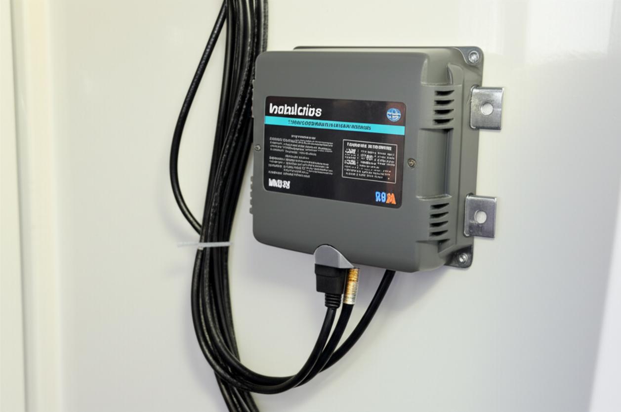
- Your boat’s schematics (if available): While not essential, a wiring diagram can help you locate the main bonding bus bar.
The Step-by-Step Continuity Test: Putting Your System to the Test
The goal here is simple: to verify there is a solid, low-resistance electrical path from every underwater metal fitting back to a central ground point. The American Boat & Yacht Council (ABYC) standard is our benchmark: the resistance should be one ohm (1 Ω) or less.
Step 1: Establish Your Ground Zero
First, identify a central point in your bonding system. This is often a main copper bus bar where many green wires converge, or you can use the bonding wire connection point on a large, accessible engine block zinc. For this test, we’ll use a main thru-hull or the rudder post as our reference point, assuming it is properly bonded.
Step 2: Set Up Your Multimeter
Turn your multimeter dial to the lowest Ohms (Ω) setting. Some meters have an audible continuity tone, which is a helpful feature. Before you start, touch your two test probes together. The meter should read very close to zero, perhaps 0.1 or 0.2 ohms. This is the internal resistance of your meter and leads; mentally subtract this value from your readings for true accuracy.
Step 3: Probing the Depths – Testing Each Component
1. Connect to Ground: Securely attach one multimeter probe (using an alligator clip is best) to your chosen ‘Ground Zero’ point. Make sure you have a clean, metal-to-metal connection.
2. Probe the Fitting: Take your other probe to the first underwater fitting you want to test (e.g., a seacock). Find a spot on the fitting’s body or flange where you can use your wire brush to create a small, clean patch of bare metal.
3. Take the Reading: Press the probe firmly against the clean spot. Observe the reading on your multimeter.
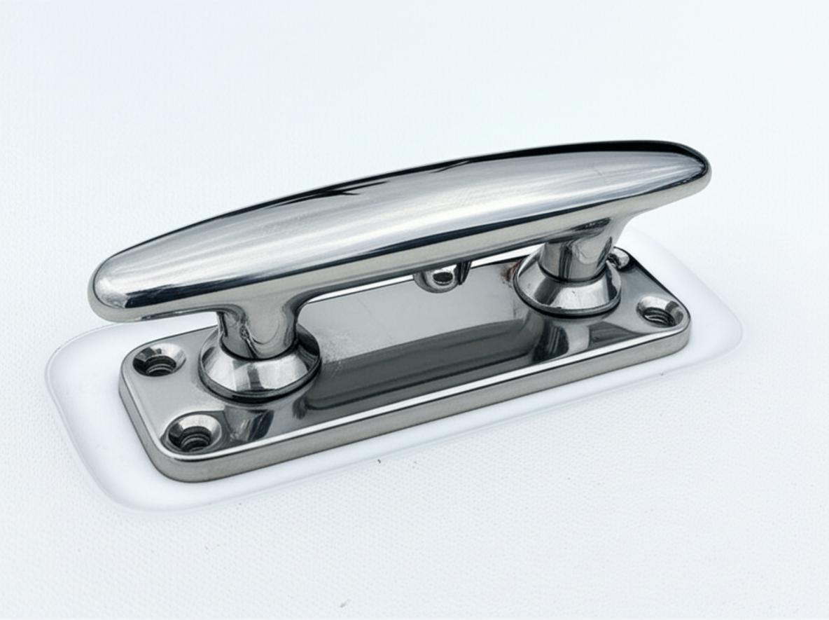
4. Repeat, Repeat, Repeat: Systematically move through the boat, testing every thru-hull, strut, rudder stock, shaft, and seacock. Don’t forget the fuel fill and deck pump-out fittings, which are also typically bonded for safety.
Interpreting the Results: What Your Meter is Telling You
This is where your detective work pays off. The numbers on the screen tell a clear story about the health of your boat’s defenses.
The Perfect Reading: Under 1 Ohm
If your meter reads 1.0 Ω or less (ideally closer to 0.1-0.2 Ω), congratulations! This component has excellent continuity with the bonding system. It is electrically connected to the anodes and is being protected. Document the reading and move to the next one.
The Problem Reading: High Resistance or ‘O.L.’
If the meter shows a high number (e.g., 50 Ω, 200 Ω) or displays ‘O.L.’ (Open Loop), you have a problem. This fitting is electrically isolated. It’s a ticking time bomb, as it is not being protected by your anodes and is highly susceptible to corrosion. The cause is almost always a failed connection. Trace the green wire from the fitting back. The culprit is usually a corroded terminal ring, a loose screw on the bus bar, or a wire that has physically broken.
Fixing a Bad Connection
To fix a high-resistance connection, disconnect the wire, thoroughly clean both the terminal and the contact point on the fitting with a wire brush, apply a light coat of dielectric grease or corrosion inhibitor, and re-fasten it securely. Test it again. Your reading should drop back into the acceptable range.
Beyond the Meter: Visual Checks and Best Practices
A multimeter test is crucial, but it should be paired with good old-fashioned visual inspection.
- Inspect Your Anodes: Check your zincs regularly. If they are more than 50% depleted, replace them. Look at the wear pattern. Even, ‘chalky’ erosion is normal. Heavy pitting or ‘cauliflower’ growth can indicate stray current issues that need immediate investigation by a qualified marine electrician.
- Trace the Wires: As you perform your continuity check, visually inspect the green bonding wires themselves. Look for signs of chafing, insulation damage, or deep corrosion, especially where they connect to terminals in the damp bilge environment.
- Consider a Galvanic Isolator: If you spend a lot of time on shore power, a galvanic isolator is a wise investment. It blocks low-level DC currents from traveling up your shore power cord, effectively isolating your boat from corrosion problems originating elsewhere in the marina.
Conclusion: Your First Line of Defense
Your boat’s bonding system is a silent guardian, working 24/7 to combat the destructive forces of corrosion. But like any guardian, it needs to be checked on. Performing a continuity test is a simple, quick, and incredibly effective piece of preventative maintenance that any boat owner can—and should—master. It empowers you to find and fix small problems before they become catastrophic failures. So, grab your multimeter this weekend. An hour of your time could save you thousands of dollars in repairs and grant you the peace of mind that comes from knowing your vessel is truly protected from the inside out.