All posts by AlvaroPrisa

Installing a shower sump pump

Tired of Soapy Scum in Your Bilge? Here’s the Fix.

There are few things less pleasant on a boat than finding a soupy, grimy mix of soapy water, hair, and who-knows-what-else sloshing around in the bottom of your bilge. For many new boat owners, the shower drain seems like a mystery—where does it all go? If the answer is “straight to the bilge,” you have a problem. This greywater cocktail not only stinks but can also clog your primary bilge pumps with hair and scum, potentially leading to catastrophic failure when you need them most. The professional solution isn’t just a good idea; it’s a necessity for a clean, safe, and well-maintained vessel: the dedicated shower sump box.

A shower sump is a self-contained box that collects greywater from your shower, sinks, and even air conditioning condensate. Inside, a small pump with an automatic float switch evacuates the water overboard through a dedicated thru-hull. It contains the mess, protects your vital bilge pumps, and keeps your boat smelling fresh. This guide will walk you through not just how to install one, but how to select the right system and install it like a seasoned marine technician, avoiding the common pitfalls that can sink an otherwise simple project.

A clean and organized boat plumbing setup featuring a shower sump pump box.

Why a Dedicated Sump is Non-Negotiable

Before we turn a single wrench, let’s be clear on why this system is so critical. Draining greywater directly into the bilge is a cardinal sin of boat ownership. Soap residue creates a film that coats everything, making bilge cleaning a nightmare. More importantly, the hair and debris will inevitably be sucked into your main bilge pump’s impeller, causing it to jam. A jammed bilge pump is a silent threat, waiting for a real emergency to reveal its failure.

Furthermore, many areas, especially no-discharge zones, have strict regulations about what can be pumped overboard. While a shower sump still pumps water overboard, it’s a contained system that prevents oily or contaminated bilge water from being discharged. It’s the responsible way to manage your boat’s greywater, keeping your bilge clean and your essential safety equipment in prime condition.

Selecting the Right Shower Sump System

You’ll generally find two paths: the all-in-one, pre-packaged sump box or a completely DIY setup. For 95% of boaters, an all-in-one kit from a reputable brand like Rule, Whale, or Jabsco is the most efficient and reliable choice. These kits come with the box, pump, and float switch already integrated.

Key Components to Scrutinize

Even with a pre-built kit, the quality of the components matters. Here’s what to look for:

  • The Box: Look for a durable ABS plastic housing with multiple inlet ports of varying sizes to accommodate different hoses. A clear, gasket-sealed lid is a must-have. It allows for quick visual inspection without having to un-plumb anything.
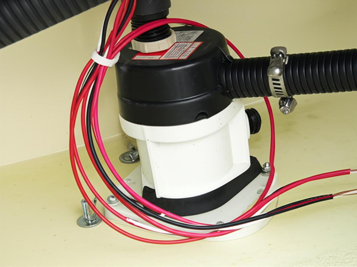
  • The Pump: Most shower sump kits come with a small centrifugal pump, typically in the 500 to 800 GPH (gallons per hour) range. This is more than adequate for handling a shower. Check that it has a built-in check valve to prevent water from flowing back into the box after the pump shuts off.
  • The Float Switch: This is the most common point of failure. Traditional mechanical float switches can get stuck or fouled by hair and soap scum. Newer systems may use electronic field-sensing switches which have no moving parts and are far more reliable. If you have a mechanical switch, ensure it has a protective cover to keep debris from jamming it.

Installation: Getting It Right the First Time

Proper installation is the difference between a set-and-forget system and a recurring headache. Take your time and do it right.

H3: Location, Location, Location

Your first task is finding the right home for the sump box. The ideal location is:

  • Low and Level: It should be installed in a low spot, but not in the very bottom of the bilge. It needs to be low enough for the shower and sink drains to feed into it via gravity.
  • Accessible: You will need to clean this box out periodically. Don’t entomb it behind a bulkhead where you can’t reach the lid. Under a cabin sole or inside a locker near the head is often a perfect spot.
  • Secure: The box must be screwed or epoxied securely to a stringer or mounting platform. A loose box sliding around at sea is a recipe for broken fittings and leaks.

H3: Plumbing the Inlets and Outlet

Plumbing is straightforward but requires attention to detail. Use smooth-bore, marine-grade sanitation hose for all connections.

Inlets: Run hoses from your shower drain and any other greywater sources to the inlet ports on the box. Ensure a constant downward slope with no dips or valleys where water can pool. Secure each connection with a high-quality stainless steel hose clamp. If an inlet port is unused, make sure it is securely capped.

Outlet: The discharge hose runs from the pump’s outlet to a dedicated thru-hull fitting above the waterline. This is the most critical part of the plumbing.

  • The Vented Loop: If your thru-hull is close to the waterline or could potentially be submerged when the boat is heeled over, you MUST install a vented loop. The loop should be mounted well above the waterline. This anti-siphon device prevents seawater from siphoning back through the pump and flooding your boat. It’s a small part that provides a huge amount of security.
  • Hose Clamps: Use two opposing stainless steel hose clamps on the thru-hull fitting. This is standard practice for any fitting that could let water into the boat.

H3: Wiring for Reliability

Faulty wiring is a fire hazard and a common cause of pump failure. Follow these marine wiring best practices:

  • Power Source: Wire the pump to a dedicated circuit on your DC panel, protected by an appropriately sized fuse or circuit breaker (check the pump’s manual for the correct amperage).
  • Wire Gauge: Use the correct gauge of marine-grade tinned wire for the amperage draw and the length of the run. A wire sizing chart is your friend here. Undersized wires will overheat and cause voltage drop, which can damage the pump motor.
  • Connections: Use marine-grade, heat-shrink crimp connectors for all connections. Never use wire nuts on a boat. They will corrode and fail. Ensure all connections are watertight and secure.
  • The Switch: Install a three-way (ON-OFF-AUTO) switch at your control panel. ‘AUTO’ allows the float switch to control the pump, ‘ON’ lets you override the switch to manually empty the box, and ‘OFF’ is for servicing.

Pro Tips and Common Pitfalls to Avoid

  • Install a Hair Strainer: The best way to keep the sump box clean is to stop hair from getting into it in the first place. A simple, effective strainer in the shower drain is your first and best line of defense.
  • Perform Regular Maintenance: The clear lid is there for a reason. Once every couple of months, open the lid, scoop out any accumulated gunk, and manually lift the float switch to ensure the pump kicks on. This five-minute check can prevent a major failure.
  • Don’t Skimp on Clamps: It’s tempting to use cheap hose clamps from the hardware store. Don’t. Invest in high-quality 316 stainless steel marine-grade clamps. They are worth every penny.
  • Avoid 90-Degree Bends: When routing your hoses, use sweeping, gentle bends instead of sharp 90-degree fittings wherever possible. This improves flow and reduces the chance of clogs.

Conclusion: A Project Worth the Effort

Installing a shower sump box may not be the most glamorous boat project, but it is one of the most satisfying. It’s a tangible upgrade that improves daily life aboard, protects critical equipment, and makes your boat cleaner and more reliable. By selecting a quality system and following proper installation practices, you can eliminate the dreaded bilge soup forever. A dry, clean bilge is a happy bilge, and this project is the best way to get there.

Bonding system continuity and corrosion checks

The Silent Ship Killer: A Boat Owner’s Guide to Bonding System Checks and Corrosion Prevention

It’s a scenario that makes any seasoned mariner shudder. You haul your boat for the season, and the once-pristine bronze thru-hull for your engine intake now looks like it’s been chewed by metallic termites—pitted, pink, and dangerously fragile. Or perhaps you notice a strange fizzing around your propeller shaft zinc just moments after plugging into shore power. These aren’t random acts of misfortune; they are the tell-tale signs of a silent, relentless process: corrosion. And your boat’s first and most important line of defense, the bonding system, might be failing its duty.

Many boat owners see the web of green wires running through their bilge and think of it as just another part of the complex electrical system. In reality, it’s a dedicated safety network designed to protect every underwater metal component from galvanic and stray current corrosion. Understanding how to test its integrity isn’t just good practice—it’s one of the most critical maintenance tasks you can perform to protect your vessel and your wallet. This guide will walk you through not just the ‘why,’ but the practical ‘how’ of testing your bonding system’s continuity.

A mechanic checks the electrical bonding system on a boat's thru-hull fitting.

What is a Bonding System and Why Should You Care?

Before we grab a multimeter, let’s get grounded in the basics. At its core, a boat’s bonding system is an electrical network that connects all major underwater metal fittings—thru-hulls, struts, rudder posts, shafts, and seacocks—to a common ground, which is then tied to your sacrificial anodes (zincs).

Demystifying the Green Wire

Think of seawater as a giant battery electrolyte. When you have two different types of metal (like a bronze propeller and a stainless-steel shaft) submerged in it, they create a small electrical current. This process, called galvanic corrosion, causes the less noble metal to sacrifice itself, corroding away to protect the more noble one. The bonding system essentially connects all these disparate metals, forcing them to share the same electrical potential. This turns your humble zinc anode into a superhero, sacrificing itself to protect every connected piece of metal, not just the one it’s bolted to.

The Two Villains: Galvanic vs. Stray Current Corrosion

Galvanic Corrosion is the slow, natural process described above. It’s predictable and managed by a healthy bonding system and properly installed anodes.

Stray Current Corrosion is the far more sinister and aggressive enemy. This occurs when direct current (DC) from a faulty wire, bilge pump, or other electrical component “leaks” into the bilge water or directly to a fitting. This stray current can eat through a thru-hull or propeller in a matter of weeks, not years. A properly functioning bonding system provides a low-resistance path for this stray current to get to ground, potentially blowing a fuse and alerting you to the problem, rather than letting it silently destroy your hardware.

Your Toolkit: Gearing Up for a Continuity Check

The good news is that you don’t need a degree in electrical engineering to perform this vital check. You just need a few basic tools:

  • A quality digital multimeter: This is the star of the show. Make sure it has a low resistance (Ohms, Ω) setting.
  • Long test leads: To reach from your central grounding point to the furthest thru-hull, you’ll need long leads. You can buy them, or easily make one by attaching alligator clips to each end of a long spool of 16-gauge wire.
  • Small wire brush or sandpaper: Corrosion and paint are insulators. You’ll need to create a clean, shiny spot on each component to get an accurate reading.
  • Contact cleaner and corrosion inhibitor spray: For cleaning and protecting connections you’ve disturbed.
  • Your boat’s schematics (if available): While not essential, a wiring diagram can help you locate the main bonding bus bar.

The Step-by-Step Continuity Test: Putting Your System to the Test

The goal here is simple: to verify there is a solid, low-resistance electrical path from every underwater metal fitting back to a central ground point. The American Boat & Yacht Council (ABYC) standard is our benchmark: the resistance should be one ohm (1 Ω) or less.

Step 1: Establish Your Ground Zero

First, identify a central point in your bonding system. This is often a main copper bus bar where many green wires converge, or you can use the bonding wire connection point on a large, accessible engine block zinc. For this test, we’ll use a main thru-hull or the rudder post as our reference point, assuming it is properly bonded.

Step 2: Set Up Your Multimeter

Turn your multimeter dial to the lowest Ohms (Ω) setting. Some meters have an audible continuity tone, which is a helpful feature. Before you start, touch your two test probes together. The meter should read very close to zero, perhaps 0.1 or 0.2 ohms. This is the internal resistance of your meter and leads; mentally subtract this value from your readings for true accuracy.

Step 3: Probing the Depths – Testing Each Component

1. Connect to Ground: Securely attach one multimeter probe (using an alligator clip is best) to your chosen ‘Ground Zero’ point. Make sure you have a clean, metal-to-metal connection.
2. Probe the Fitting: Take your other probe to the first underwater fitting you want to test (e.g., a seacock). Find a spot on the fitting’s body or flange where you can use your wire brush to create a small, clean patch of bare metal.
3. Take the Reading: Press the probe firmly against the clean spot. Observe the reading on your multimeter.
4. Repeat, Repeat, Repeat: Systematically move through the boat, testing every thru-hull, strut, rudder stock, shaft, and seacock. Don’t forget the fuel fill and deck pump-out fittings, which are also typically bonded for safety.

Interpreting the Results: What Your Meter is Telling You

This is where your detective work pays off. The numbers on the screen tell a clear story about the health of your boat’s defenses.

The Perfect Reading: Under 1 Ohm

If your meter reads 1.0 Ω or less (ideally closer to 0.1-0.2 Ω), congratulations! This component has excellent continuity with the bonding system. It is electrically connected to the anodes and is being protected. Document the reading and move to the next one.

The Problem Reading: High Resistance or ‘O.L.’

If the meter shows a high number (e.g., 50 Ω, 200 Ω) or displays ‘O.L.’ (Open Loop), you have a problem. This fitting is electrically isolated. It’s a ticking time bomb, as it is not being protected by your anodes and is highly susceptible to corrosion. The cause is almost always a failed connection. Trace the green wire from the fitting back. The culprit is usually a corroded terminal ring, a loose screw on the bus bar, or a wire that has physically broken.

Fixing a Bad Connection

To fix a high-resistance connection, disconnect the wire, thoroughly clean both the terminal and the contact point on the fitting with a wire brush, apply a light coat of dielectric grease or corrosion inhibitor, and re-fasten it securely. Test it again. Your reading should drop back into the acceptable range.

Beyond the Meter: Visual Checks and Best Practices

A multimeter test is crucial, but it should be paired with good old-fashioned visual inspection.

  • Inspect Your Anodes: Check your zincs regularly. If they are more than 50% depleted, replace them. Look at the wear pattern. Even, ‘chalky’ erosion is normal. Heavy pitting or ‘cauliflower’ growth can indicate stray current issues that need immediate investigation by a qualified marine electrician.
  • Trace the Wires: As you perform your continuity check, visually inspect the green bonding wires themselves. Look for signs of chafing, insulation damage, or deep corrosion, especially where they connect to terminals in the damp bilge environment.
  • Consider a Galvanic Isolator: If you spend a lot of time on shore power, a galvanic isolator is a wise investment. It blocks low-level DC currents from traveling up your shore power cord, effectively isolating your boat from corrosion problems originating elsewhere in the marina.

Conclusion: Your First Line of Defense

Your boat’s bonding system is a silent guardian, working 24/7 to combat the destructive forces of corrosion. But like any guardian, it needs to be checked on. Performing a continuity test is a simple, quick, and incredibly effective piece of preventative maintenance that any boat owner can—and should—master. It empowers you to find and fix small problems before they become catastrophic failures. So, grab your multimeter this weekend. An hour of your time could save you thousands of dollars in repairs and grant you the peace of mind that comes from knowing your vessel is truly protected from the inside out.

Integrating a GPS chartplotter with an autopilot

Unlock Your Helm: A Sailor’s Guide to Seamless GPS Chartplotter and Autopilot Integration

There’s a moment on any long passage, often in the dead of night with the sea hissing along the hull, when you truly appreciate the silent, tireless crew member at the helm: the autopilot. But an autopilot steering a simple compass course is just a helmsman. When you integrate it with your GPS chartplotter, it becomes a master navigator. This synergy transforms two separate pieces of hardware into a sophisticated, unified system that can steer your vessel with remarkable precision, improving safety, efficiency, and your overall enjoyment on the water. This guide is about moving beyond the basic connection and mastering this integration to truly unlock your helm.

A modern yacht helm station showing an integrated GPS chartplotter and autopilot controls.

Why Integrate? Moving Beyond ‘Point and Steer’

A standalone autopilot is a fantastic tool. You set a heading—say, 270 degrees magnetic—and it holds that course, compensating for yaw and minor wave action. But it’s blind. It doesn’t know about the 2-knot cross-current pushing you south or the waypoint you’re actually trying to reach. It just steers a number.

Integrating the autopilot with a GPS chartplotter elevates the game entirely. The chartplotter becomes the ‘brain,’ and the autopilot becomes the ‘muscle.’ The plotter knows the destination, the planned route, and your real-time position on the chart. It feeds a constant stream of navigational data to the autopilot, which then makes intelligent steering adjustments. This is the difference between steering a compass course and steering a course over ground to a destination.

The Core Benefits of a Unified System

  • Pinpoint Navigational Accuracy: The system doesn’t just steer toward a waypoint; it works to eliminate Cross-Track Error (XTE). This means it actively steers the boat back onto the plotted route line, compensating for wind (leeway) and current (set). This is invaluable for staying within narrow channels or avoiding charted hazards.
  • Fuel and Time Efficiency: By constantly correcting to follow the most direct, pre-planned route, the system prevents the subtle, cumulative wanderings that happen with manual steering or a simple compass course. Over a long passage, this translates directly into saved fuel for powerboats and shorter passage times for all vessels.
  • Reduced Helm Fatigue: This is arguably the most significant benefit. On long watches or when sailing short-handed, the integrated system reliably manages the helm. This frees up the watchkeeper to focus on other critical tasks: sail trim, collision avoidance, monitoring weather, or simply getting much-needed rest. A well-rested skipper is a safe skipper.
  • Enhanced Safety Features: Modern chartplotters often have dedicated Man Overboard (MOB) functions. With an integrated system, a single button press can create an immediate waypoint at the MOB position and command the autopilot to execute a recovery pattern, like a Williamson Turn, steering you back to the location with precision.

The Nuts and Bolts: Understanding the Connection

For modern marine electronics, the magic happens over a network. While older systems used a more cumbersome protocol, today’s standard makes setup relatively straightforward.

The NMEA 2000 Backbone: Your Boat’s Digital Nervous System

Think of NMEA 2000 (often shortened to N2K) as a simple, robust network for your boat. It’s a ‘plug-and-play’ system consisting of a main cable (the backbone) with T-connectors that allow individual devices (like your plotter, autopilot, GPS antenna, and wind instruments) to plug in via drop cables. For this network to function, it must be powered and have a 120-ohm terminator resistor at each end of the backbone. A properly installed N2K backbone is the foundation of a reliable integrated navigation system. It allows all your electronics to talk to each other seamlessly.

What Data is Being Shared?

The chartplotter and autopilot are in constant communication. The chartplotter sends critical navigation data PGNs (Parameter Group Numbers) to the autopilot, including:

  • Bearing to Waypoint (BTW): The direction to the next point in your route.
  • Cross-Track Error (XTE): How far you are, left or right, from the intended route line.
  • Route Information: The complete list of waypoints for the autopilot to follow sequentially.

In return, the autopilot’s core components, like its high-accuracy compass and rudder feedback sensor, send data back to the chartplotter, which can be displayed on screen.

On-the-Water Best Practices for Flawless Performance

Connecting the devices is only half the battle. To get the most out of your system, you need to use it intelligently.

Calibration is Absolutely Non-Negotiable

An uncalibrated autopilot is an unreliable one. After installation, you must perform the sea trial calibration. This involves a series of turns and maneuvers that allow the system to learn your boat’s specific handling characteristics. It also includes ‘swinging the compass’ to correct for any magnetic deviation on your vessel. You will also need to configure the autopilot’s response levels or sea-state settings. A twitchy, aggressive response might be fine on a calm day but will be inefficient and jerky in heavy seas. Take the time to get this right; it pays dividends in performance.

Plan Your Route, Then Engage

Never engage the autopilot on a route you haven’t thoroughly reviewed. Before leaving the dock, build your route on the chartplotter. Zoom in on every leg. Check for depths, obstructions, shipping lanes, and other hazards. When you engage the autopilot, you are entrusting it to follow this plan. Ensure the plan is a safe one. When activating, there’s a key difference between ‘Go To Waypoint’ and ‘Follow Route.’ The former is a direct line, while the latter will follow the specific legs you’ve created—the safer option in almost every scenario.

Know When *Not* to Use It

An integrated autopilot is a tool, not a replacement for good seamanship. There are times when you must take manual control:

  • Close-Quarters Maneuvering: Never use the autopilot in crowded harbors, marinas, or tight anchorages.
  • Heavy Traffic: In areas with dense vessel traffic, you need the instant response of manual steering to make collision-avoidance maneuvers.
  • Unpredictable, Heavy Seas: In very rough and confused seas, an experienced hand on the helm is often better at anticipating wave patterns and surfing safely down a wave face.

The golden rule: The autopilot is steering, but the skipper is always in command and the watchkeeper is always on watch.

Conclusion: Your Smartest Crew Member

Properly integrating your GPS chartplotter and autopilot does more than just free you from standing at the helm. It creates a powerful, intelligent navigation system that steers more accurately and efficiently than most humans can over long periods. It reduces fatigue, increases situational awareness by freeing you up to keep a better lookout, and ultimately makes your time on the water safer and more enjoyable. By understanding the principles behind the connection and adhering to best practices on the water, you can transform this electronic duo into your most trusted and reliable crew member.

Safe Transfer of an 85-Foot Lamberti to the Shipyard — Crew & Inspection by Prisa Yachts

Moving an 85-foot Lamberti to a shipyard isn’t a casual harbor hop. Yard schedules are tight, channels can be narrow and busy, and low-speed handling reveals issues that never show in a sea trial. Prisa Yachts delivers a qualified delivery crew paired with a structured inspection, so your yard period starts safely, on time, and with clear documentation.

Why a Yard Run Is Different

A yard approach concentrates risk in the last mile: limited maneuvering room, cross-winds or current, traffic, and strict haul-out slots. Small oversights (a soft thruster, a hot running gear seal, a clogged strainer) can snowball at the pier. Our process reduces variables before lines come off.

Two Pillars: Qualified Crew + Structured Inspection

1) Qualified Delivery Crew.
We staff with licensed professionals experienced in 80–100 ft yachts and tight-quarters operations:

  • Captain (large-yacht handling, docking plans, contingency calls)
  • Mate/Engineer (live systems monitoring, troubleshooting, checklists)
  • Deckhand (fenders, lines, clear communications at close range)
    Where prudent, we add a local pilot or tug standby for cross-current basins or confined fairways.

2) Structured Inspection (Pre-Departure & Pre-Dock).
Our checklist focuses on what matters for low-speed control and safe intake:

  • Propulsion & Steering: helm hard-over timing, rudder indicator correlation, electronic control response
  • Cooling & Fuel: raw-water flow at idle and maneuvering rpm; filter condition and differential pressure
  • Electrical & Nav: thrusters under load, windlass breaker, redundant comms, nav backup
  • Deck Readiness: fender plan by side, spring line order, tug/assist points
  • Emergency Gear: bilge pumps/manual backups, fire stations, E-stop familiarity

Outcome: a yacht that’s not only running, but ready for a controlled, low-speed approach in a busy yard.

How We Execute

  • Planning Window: route, tides, bridge openings, VTS advisories; we target slack water for the final approach.
  • Departure: engines warm, thrusters tested, comms check complete, fendering pre-rigged for berth changes.
  • En-Route: engineer tracks temps/pressures/flows while the bridge maintains conservative speed and stopping margins.
  • Approach & Docking: briefed hand signals, spring-line order, and pre-agreed go-around criteria; deck keeps fenders live and mobile.
  • Handover: we deliver a Condition & Handover Report (photos, hour meters, recommended yard checks).

What You Receive

  • Crewed transfer (Captain + Mate/Engineer + Deck as required)
  • Inspection report (pre-departure and arrival notes with photos)
  • Passage plan (route, timing, tide/bridge info, yard coordination)
  • Clean handover (documented condition, snags for yard attention)

Why Prisa Yachts

Yard time is expensive; last-mile mishaps are avoidable. Our combination of professional crewing and a disciplined inspection routine keeps your Lombardi’s transfer predictable, documented, and on schedule.

Book your yard transfer with Prisa Yachts—arrive safely, cleanly, and ready to work.

Electric vs. gas galley installations on boats

The All-Electric Galley: Is It Time to Ditch Propane on Your Boat?

For decades, the rhythmic hiss of a propane stove and the gentle clatter of a gimballed grate have been the quintessential soundtrack to a cruising boat’s galley. Propane has been a reliable, if sometimes fussy, partner for sailors cooking at sea. But a quiet revolution is taking place below decks, powered by advancements in battery technology and high-efficiency appliances. More and more boat owners are asking the question: Is it finally time to cut the gas line and embrace an all-electric galley?

The move from gas to electric is more than just a preference; it’s a fundamental shift in how we manage energy and safety onboard. It’s about trading the periodic anxiety of propane leak checks for the silent, efficient power of induction. This isn’t a simple appliance swap, however. It’s a holistic system upgrade that demands careful planning. Let’s weigh anchor and navigate the real-world considerations of making the switch.

Modern electric galley on a sailboat with induction cooktop and sleek countertops

The Case Against Propane: Why Sailors Are Reconsidering Gas

Before we dive into the allure of electric, it’s important to understand the push factors. Why are seasoned mariners, long accustomed to propane, looking for an alternative? The reasons generally fall into three categories: safety, convenience, and comfort.

The Unspoken Safety Concerns

Let’s be blunt: propane (LPG) is a heavy, highly flammable gas stored under pressure. On a boat, it demands respect and constant vigilance. A proper marine installation includes a dedicated, ABYC-compliant locker that vents overboard, a remote solenoid shut-off valve, and high-quality, chafe-protected lines. Even with a perfect system, the risk of a leak, however small, is always present. Since propane is heavier than air, any escaped gas will sink into the bilge, creating a potential explosion hazard just waiting for a spark. This inherent risk is the number one reason sailors dream of a gas-free boat.

The Convenience Conundrum

Anyone who has cruised internationally knows the frustration of sourcing propane. Bottle fittings and standards vary wildly from country to country, leading to a collection of questionable adapters or the expensive task of acquiring new tanks. It’s a logistical headache that an all-electric system simply eliminates. Furthermore, that dedicated propane locker, while essential for safety, consumes valuable deck or cockpit space that could be repurposed for other gear.

The Heat and Humidity Issue

A often-overlooked byproduct of burning propane is water vapor. Every flame on your stove is releasing moisture directly into your cabin, adding to the ever-present battle against dampness and mildew. On a hot, tropical evening, the ambient heat radiating from a gas stove can also turn the salon into a sauna. An electric galley significantly reduces both of these comfort-killing factors.

The All-Electric Promise: What’s Driving the Change?

The dream of an all-electric galley isn’t new, but until recently, it was impractical for most cruising boats due to power limitations. Two key technological advancements have changed the game entirely.

Induction Cooking: The Heart of the Modern Galley

Induction cooktops are the star players in the electric galley. Unlike traditional electric resistance burners that glow red-hot, induction uses a magnetic field to directly heat the cookware itself. The benefits at sea are massive:

  • Efficiency: Around 85-90% of the energy goes directly into the pot, compared to about 40-50% for gas. This means faster boiling times and less wasted energy.
  • Safety: The cooktop surface stays relatively cool to the touch, drastically reducing the risk of burns. When you remove the pot, the heating stops instantly.
  • Comfort: With almost no waste heat, the galley stays much cooler.
  • Cleaning: A flat, smooth glass surface is infinitely easier to wipe down than a complex gas hob with grates and burners.

The Power Revolution: Lithium (LiFePO4) Batteries

Induction’s high efficiency is great, but it still requires a significant burst of power. This is where older battery technologies, like lead-acid, would falter. The real enabler of the all-electric galley is the rise of Lithium Iron Phosphate (LiFePO4) batteries. They possess the high energy density and, crucially, the high discharge rate capability to power an induction hob and a microwave without damaging the battery bank. They provide the deep, reliable power reservoir needed to make electric cooking a daily reality, not just an occasional luxury when plugged into shore power.

The Reality Check: Planning Your All-Electric Conversion

Tearing out the gas lines is tempting, but a successful conversion requires a systems-based approach. Simply installing an induction cooktop without upgrading the infrastructure is a recipe for frustration.

Step 1: Conduct a Thorough Energy Audit

You cannot guess at your power needs. You must calculate them. An all-electric galley is a power-hungry beast. Start by estimating your cooking usage. A 1500-watt induction burner running for 20 minutes to boil water and cook pasta consumes 500 watt-hours. At 12 volts, that’s roughly 42 amp-hours (Ah) from your battery bank. Do that three times a day, add in a microwave, and you can see how quickly the consumption adds up. For most cruising couples, a LiFePO4 bank of 400Ah is a realistic minimum, with 600-800Ah being a more comfortable target for serious cooking.

Step 2: Plan Your Charging Strategy

A huge battery bank is useless if you can’t refill it. Your charging system must be able to keep up with your new, higher demand. This usually means a multi-pronged approach:

  • Solar: This will be your primary workhorse at anchor. A significant array of 400-800 watts or more, managed by a quality MPPT charge controller, is essential.
  • Alternator: When motoring, a high-output alternator (120A+) paired with an external regulator that is optimized for lithium charging is key to replenishing the bank quickly.
  • Generator/Shore Power: For extended periods of bad weather or heavy usage, a small generator or the ability to plug into shore power provides a necessary backup.

Step 3: Choose the Right Appliances

With power sorted, you can select your hardware. You’ll need more than just a cooktop.

  • Inverter: A high-output, pure sine wave inverter is non-negotiable. This device converts your 12V DC battery power to 120V/230V AC for your appliances. A 2000-watt unit is a bare minimum, but a 3000-watt inverter/charger is a more robust choice that can handle multiple loads.
  • Cooktop: Choose a marine-grade or high-quality residential single or double-burner induction unit. Pay attention to its maximum wattage to ensure your inverter can handle it.
  • Other Appliances: A combination microwave/convection oven is a popular, space-efficient choice to replace a traditional gas oven. Electric kettles and toaster ovens also become viable options.

Conclusion: Is the Future of Your Galley Electric?

Making the switch to an all-electric galley is a significant undertaking, both technically and financially. The upfront cost of a substantial LiFePO4 battery bank, a large inverter, solar panels, and new appliances is considerable. It is not a weekend project.

However, the rewards are equally significant. The payoff comes in the form of enhanced safety by removing a volatile gas from your living space, unparalleled convenience with a single fuel source for all your systems, and a cleaner, cooler, and more comfortable cooking environment. For the modern cruiser investing in a robust electrical system, the all-electric galley is no longer a futuristic concept—it’s a logical, safer, and ultimately more enjoyable evolution of life at sea.

Sanitation system check-valves inspection

The Unsung Heroes of Your Head: A Guide to Marine Sanitation Check-Valve Inspection

There are few things on a boat that can sour a perfect day on the water faster than a misbehaving marine head. That faint, unpleasant odor you can’t quite trace, or the slow, creeping return of water into the bowl after you’ve pumped it dry – these are the classic signs that a tiny, yet critical, component in your sanitation system is failing. We’re talking about the check-valve, most famously the ‘joker valve’.

Ignoring this small rubber part is a mistake many a skipper has made, often leading to a messy, foul-smelling, and entirely preventable repair job. This guide isn’t just about fixing a problem; it’s about understanding the system, performing preventative inspections, and ensuring your marine toilet operates reliably, trip after trip. Consider this your definitive playbook for keeping the backflow at bay.

A view of a marine sanitation hose and valve system on a boat, highlighting the complexity of boat plumbing.

Understanding the Enemy: What Are Check-Valves and Why Do They Fail?

At its core, a check-valve is a one-way gate. In a marine sanitation system, its job is to allow waste and water to be pumped out of the toilet bowl and down the discharge line, while preventing anything from flowing back. The most common and crucial of these is the joker valve.

The Joker Valve: Your First Line of Defense

Named for its resemblance to the pointed hat of a court jester, the joker valve is a cone-shaped rubber component with a slit or ‘duckbill’ at the end. When you pump the head, the pressure forces the lips of the valve open to let waste pass through. As soon as the pressure subsides, the natural elasticity of the rubber snaps the lips shut, forming a seal. It’s a simple, brilliant design, but it’s also the system’s weakest link.

The Common Culprits of Failure

Joker valves live in a harsh environment and don’t last forever. Understanding why they fail is the first step to preventing it:

  • Calcification: The combination of urine and saltwater creates a stubborn calcium scale, not unlike concrete. This scale builds up on the joker valve’s lips, preventing them from closing completely. This is, by far, the most common cause of failure.
  • Foreign Objects: A marine head is designed for human waste and marine-grade, rapidly dissolving toilet paper—and nothing else. Conventional toilet paper, paper towels, or sanitary products will not break down and will inevitably get caught in the valve, holding it open.
  • Age & Material Fatigue: Over time, the rubber loses its elasticity. It can become brittle, hard, or simply too weak to form a tight seal. A valve that is several years old is living on borrowed time.
  • Chemical Damage: Harsh chemical cleaners, solvents, or bleach can destroy the rubber, causing it to swell or disintegrate. Only use cleaners specifically formulated for marine sanitation systems.

The Inspection Playbook: A Step-by-Step Guide

Inspecting your joker valve should be on your annual maintenance checklist, or done immediately if you notice symptoms. It’s not the most glamorous job, but with the right preparation, it’s manageable.

Gear Up: Tools and Safety Precautions

Before you open any part of the sanitation system, assemble your gear. Safety and hygiene are paramount.

  • Safety First: Heavy-duty nitrile or rubber gloves are non-negotiable. Safety glasses are a very good idea.
  • Tools: You’ll likely need a set of screwdrivers and perhaps a small wrench or pliers, depending on your head model.
  • Supplies: A bucket, plenty of rags, a small brush, and white vinegar for cleaning.
  • The All-Important Spare: Have a brand-new, correct-model joker valve (and ideally a full service kit) on hand before you start. Never disassemble the head without a replacement ready to go.

Step 1: System Shutdown and Preparation

First, close both the raw water intake and the waste discharge seacocks. Pump the head completely dry. To make the job infinitely more pleasant, flush the system several times with fresh water before you begin disassembly. This will clear the lines of most of the unpleasant contents.

Step 2: Gaining Access to the Valve

The joker valve is typically located in the discharge elbow of the pump assembly. On most manual heads (like the popular Jabsco models), you’ll need to remove the 4 to 6 screws holding the pump assembly to the toilet base. Carefully lift the pump off. Be prepared for a small amount of residual water to spill out—have your rags and bucket ready.

Step 3: The Visual and Tactile Inspection

Once the pump is removed, you can look inside the discharge port and see the joker valve. Carefully pull it out. Now, perform a thorough inspection:

  • Look for Damage: Check for any rips, tears, or pinholes in the rubber.
  • Check for Debris: Look for any scale, hair, or paper caught between the lips. Sometimes, simply cleaning it is enough, but this is rare.
  • The Squeeze Test: A healthy joker valve should be soft and pliable. Squeeze it gently. The lips should spring back together instantly to form a perfect seal. If the material feels stiff, hard, or brittle, it’s time for a replacement.
  • Check for Distortion: If the valve is warped or no longer holds its conical shape, it cannot seal properly.

The “When in Doubt, Swap it Out” Rule

Here’s the most important piece of advice: Joker valves are inexpensive wear items. They cost a fraction of the value of your time and peace of mind. If you’ve gone to the trouble of taking the head apart, and the valve looks even slightly suspect, replace it. It is cheap insurance against having to do this messy job all over again in a few months.

Proactive Maintenance: Preventing Future Failures

The best repair is the one you never have to do. A few simple habits can dramatically extend the life of your sanitation system components.

The Right Diet for Your Head

Be vigilant about what goes into the toilet. Use only marine-grade toilet paper, and use it sparingly. Educate all guests on this rule. A small, polite sign in the head compartment can work wonders.

Regular Descaling: The Vinegar Trick

Calcium scale is your primary enemy. To combat it, flush the system regularly with white vinegar. Once a month, close the intake seacock, pump the bowl dry, and pour in about a pint of white vinegar. Pump it just enough to move it into the hoses and let it sit for several hours (or overnight) before flushing it through. This will dissolve minor scale deposits before they become major blockages.

Keep Spares, Keep Your Sanity

A failed head can ruin a weekend cruise. Every boat owner should have at least two spare joker valves and a complete pump service kit for their specific model stored on board. They take up minimal space and can turn a trip-ending disaster into a 30-minute inconvenience.

Conclusion: Master of Your Marine Domain

The marine sanitation system is often out of sight and out of mind, until it fails. By understanding the critical role of the humble check-valve and adopting a proactive inspection and maintenance schedule, you take control. This isn’t just about avoiding foul odors; it’s about being a competent, self-sufficient skipper who understands their vessel from stem to stern. A little attention to this unglamorous system pays huge dividends in reliability and peace of mind on the water. Fair winds and a trouble-free head!

Check Periodically the Stainless Steel Fittings

More Than a Shine: A Sailor’s Guide to Inspecting Stainless Steel Hardware

There’s nothing quite like the brilliant glint of polished stainless steel against a deep blue sea. It speaks of strength, reliability, and modern seamanship. From the stanchions guarding our decks to the chainplates holding our masts aloft, we place immense trust in these metallic components. But here’s a hard-won piece of sea wisdom: that beautiful shine can be deceiving. Stainless steel, despite its name, is not invincible. In the harsh marine environment, it can and does corrode, crack, and fail—often silently, until it’s too late. A routine inspection of your boat’s hardware is not just a ‘nice-to-do’ task for a quiet Sunday; it’s a fundamental pillar of safe boating.

A collection of marine-grade stainless steel hardware, including turnbuckles and shackles, ready for inspection.

Understanding Marine-Grade Stainless Steel

Before we can properly inspect it, we need to understand what we’re looking at. The term “stainless steel” covers a wide family of alloys, but for marine use, two grades are paramount.

Not All Stainless Is Created Equal: 304 vs. 316

You’ll often encounter Type 304 stainless in general applications. It’s tough and corrosion-resistant in many environments, but it has an Achilles’ heel: chlorides. Saltwater is a chloride-rich soup, and 304 will eventually succumb to pitting and crevice corrosion. For any application on a boat that sees salt spray, and especially for critical components, you need Type 316. The key difference is the addition of a little element called molybdenum. This addition dramatically increases its resistance to chlorides, making 316 the undisputed king for marine hardware. If you’re replacing a fitting, always insist on 316 or its low-carbon variant, 316L.

The Myth of “Stainless”

The magic of stainless steel lies in a microscopic, invisible layer of chromium oxide that forms on its surface when exposed to oxygen. This “passive layer” is what protects the iron in the steel from rusting. The problem is, this protective layer can be damaged. Mechanical scratches, contamination with carbon steel (like from using a steel wire brush), or, most commonly, a lack of oxygen in tight crevices, can break down this barrier and allow corrosion to begin its insidious work.

The Telltale Signs of Trouble: What to Look For

Developing a keen eye for the subtle signs of stainless steel degradation is one of the most valuable skills a skipper can possess. Grab a good flashlight, a magnifying glass, and let’s go on a hunt.

Surface Stains: The Early Warning

Often called “tea staining,” this is a light, reddish-brown surface discoloration. While often cosmetic, you should never ignore it. It can be an early indicator of a poor-quality alloy (perhaps 304 masquerading as 316), contamination, or the beginning of more serious issues. It’s most common in areas that don’t get a regular freshwater rinse. A good polish with a specialized cleaner can often remove it, but note the location and keep a close eye on it.

Crevice Corrosion: The Hidden Danger

This is one of the most common and dangerous forms of failure. It occurs in oxygen-starved environments, such as under the head of a bolt, beneath a washer, between the threads of a turnbuckle, or where a chainplate passes through the deck. Water gets trapped, the oxygen is consumed, and the passive layer breaks down, creating an acidic environment that aggressively attacks the steel. The telltale sign is a weeping rust stain emanating from the joint. If you see this, that fitting needs to be disassembled, inspected, and likely replaced immediately.

Pitting: Small Holes, Big Problems

Pitting is localized corrosion that creates small, deep cavities in the steel. A few tiny pits on a cleat might not be a major concern, but on a high-load component like a rigging terminal or a prop shaft, they can act as stress risers, becoming the starting point for a stress crack. Pitting indicates that the passive layer has been compromised in specific spots, often due to microscopic imperfections in the metal or prolonged exposure to stagnant saltwater.

Stress Corrosion Cracking (SCC) and Fatigue: The Silent Catastrophe

This is the one that keeps riggers up at night. SCC is the formation of microscopic cracks in metal that is under tensile stress in a corrosive environment—a perfect description of a boat’s rigging. These cracks can propagate with no obvious outward sign of corrosion, leading to sudden, catastrophic failure. You need a magnifying glass to even have a chance of spotting them. Look for them in high-stress areas: the bends of chainplates, around swage fittings, and on toggle pins. If you suspect SCC on a critical component, the only safe course of action is replacement or professional non-destructive testing, such as dye penetrant inspection.

A Practical Inspection Checklist

Make this a part of your regular maintenance schedule—at least twice a season, and before any major passage.

Deck Hardware & Rigging

  • Stanchions and Lifelines: Vigorously wiggle each stanchion. Check the bases for fine, hair-like cracks radiating from the mounting bolts. Inspect lifeline terminals (swaged or mechanical) for any signs of cracking or corrosion.
  • Chainplates: This is ground zero for potential failure. On deck, check the sealant for any breaks. Look for fine cracks where the plate bends. Below deck, use a mirror and flashlight to inspect the entire length. Any weeping rust stains are a major red flag that crevice corrosion is at work where you can’t see it.
  • Turnbuckles: At least annually, slacken your rigging and unwind every turnbuckle. Clean the threads thoroughly and inspect them for corrosion and galling (where the threads bind and tear). Lubricate with a suitable anti-seize compound before re-tuning.
  • Shackles, Blocks, and Toggles: Check shackles for any signs of elongation or deformation—a sign they have been overloaded. Ensure clevis pins are straight and cotter pins are sound. The sheaves in blocks should turn freely.

Hull and Systems

  • Thru-Hulls and Seacocks: While less common in stainless, inspect any such fittings for pitting and crevice corrosion, especially around the flange.
  • Prop Shaft and Rudder Stock: During haul-out, carefully inspect shafts for any pitting or signs of galvanic corrosion, especially near the prop or any bearings.

Prevention: The Best Maintenance Strategy

An ounce of prevention is worth a ton of cure, especially at sea.

  • Freshwater Rinse: The simplest and most effective preventative measure. A thorough freshwater washdown after every sail removes the corrosive salt deposits.
  • Clean and Passivate: Regularly clean your stainless with a proper marine-grade cleaner (never use steel wool or carbon steel brushes!). To restore the protective layer, you can use a mild acid like oxalic acid, which will remove surface impurities and allow the chromium oxide layer to reform perfectly.
  • Proper Bedding: Ensure all deck hardware is bedded with a high-quality marine sealant. This prevents water intrusion, which is the root cause of crevice corrosion. Dig out and replace any old, cracked sealant.

Conclusion: Trust, but Verify

Your boat’s stainless steel hardware is the silent workhorse that keeps your rig standing and your crew safe. It withstands incredible forces in a relentlessly corrosive environment. But it requires your attention and your diligence. Don’t be lulled into a false sense of security by a pretty shine. Get out there, look closely, and learn the language of your hardware. A few hours of careful inspection can be the difference between a safe passage and a catastrophic failure. Trust your hardware, but always, always verify.

Marine Air Conditioner Installation

Beat the Heat: A Comprehensive Guide to Installing Marine Air Conditioning

There are few things less enjoyable than being trapped in a sweltering, humid cabin after a perfect day on the water. The air gets thick, cushions feel damp, and sleeping becomes a sticky, restless affair. This is where a marine air conditioning system transforms from a luxury into a near necessity. It’s not just about comfort; it’s about protecting your boat’s interior from mildew and making your time aboard truly relaxing. But installing one isn’t as simple as plugging in a window unit from a hardware store. Marine AC installation is a serious project that demands careful planning and a deep respect for the unique challenges of the marine environment.

As a marine professional who has seen countless installations—both good and bad—I’ve created this guide to walk you through the entire process. We’ll cover everything from choosing the right system to the critical details that separate a reliable, efficient installation from a future headache.

Why You Can’t Just Use a Household AC Unit

Before we dive in, let’s clear up a common question: “Can I just install a cheap portable or window AC unit on my boat?” The answer is an emphatic no. A boat is a harsh environment, and marine-grade equipment is built to survive it. Here’s why a standard unit will fail:

  • Corrosion: The salty, humid air will rapidly corrode the coils and electronics of a residential unit. Marine systems use specialized materials like cupronickel for condenser coils and stainless steel components to resist saltwater corrosion.
  • Cooling Method: Marine ACs don’t use a fan to cool the condenser like a home unit. They use a continuous flow of raw seawater, which is a far more efficient method of heat exchange. This requires a thru-hull, pump, and plumbing that household units lack.
  • Condensate Management: Boats move, heel, and rock. Marine AC units are designed with deep, robust condensate pans and drains to manage the water they pull from the air, preventing spills that can lead to bilge water, mold, and rot.
  • Durability: Everything on a boat gets shaken and slammed around. Marine systems are built to withstand the constant vibration and shock of life at sea.

Choosing Your Weapon: Types of Marine AC Systems

The right system for your vessel depends on its size, layout, and your budget. The three main types are self-contained, split-gas, and chilled water systems.

Self-Contained Units

This is the most common type for boats under 40-45 feet. The entire system—compressor, condenser, and evaporator—is housed in a single chassis. You install the unit in the living space (often under a settee or in a locker) and run ductwork to one or more vents.

  • Pros: Relatively simple to install, cost-effective, and compact. They are the go-to choice for most DIY installations.
  • Cons: The compressor is in your living space, so they can be noisier than other options. They are also less efficient for cooling multiple, separate cabins.

Split-Gas Systems

Similar to central air in a home, these systems separate the components. The noisy condenser/compressor unit is installed in a mechanical space like the engine room, while one or more quiet air handlers are placed in the cabins. Refrigerant lines connect the two parts.

  • Pros: Much quieter in-cabin operation and offer great flexibility for cooling multiple areas.
  • Cons: Installation is significantly more complex and expensive. It requires handling refrigerant, which legally requires an EPA-certified technician in many places. This is rarely a DIY job.

Chilled Water Systems

Found on larger yachts and commercial vessels, these are the pinnacle of marine climate control. A large chiller in the engine room cools a closed loop of fresh water (mixed with glycol), which is then pumped throughout the vessel to individual air handlers in each cabin. These systems can also provide reverse-cycle heating very efficiently.

  • Pros: Extremely efficient, quiet, and scalable for any size vessel.
  • Cons: By far the most complex and expensive to install and maintain. Strictly a job for specialized professionals.

The Installation Blueprint: Planning is Everything

A successful installation is 90% planning. Rushing this stage is a recipe for disaster. Here’s your pre-installation checklist.

1. Sizing the Unit: The BTU Game

Choosing the right capacity, measured in BTUs (British Thermal Units), is critical. Too small, and it will run constantly without cooling the boat. Too large, and it will short-cycle, failing to dehumidify the air properly and causing premature wear. A rough rule of thumb is 14-16 BTUs per cubic foot of cabin space. However, you must adjust for:

  • Windows and Hatches: Large, unshaded windows add a significant heat load.
  • Sun Exposure: A boat with a dark hull or deck will get much hotter.
  • Location: A boat in the tropics needs more cooling power than one in New England.
  • Insulation: Well-insulated hulls require less BTU capacity.

Consult the manufacturer’s guidelines carefully. When in doubt, it’s better to be slightly undersized than oversized.

2. Location, Location, Location

Where you place the components is just as important as the unit itself.

  • The Main Unit (Self-Contained): Find a spot that is low in the boat, central to the area you want to cool, and has space for ducting. Under a berth or settee is common. Crucially, ensure you have easy access for maintenance and a clear path for the condensate drain.
  • Return Air: The unit needs to draw in warm cabin air. This return vent should be as large as possible and unobstructed. Never install the unit in an engine room where it could pull in fumes.
  • Supply Vents: Position your cool air supply vents high in the cabin, as cool air sinks. Aim for a circular airflow pattern, with the supply and return vents at opposite ends of the space.

3. The Seawater Circuit: The Heart of the System

This is the most critical part of the installation. A failure here can sink your boat.

  • Thru-Hull & Seacock: The water intake must be a dedicated thru-hull fitting with a proper marine seacock. It should be located where it will remain submerged even when the boat is heeling or planning.
  • Sea Strainer: A sea strainer is non-negotiable. It must be installed between the seacock and the pump to protect the pump and condenser coils from debris. Mount it above the waterline for easy cleaning.
  • Pump: The circulation pump must be mounted below the waterline to ensure it stays primed.
  • Hoses & Clamps: Use high-quality reinforced marine hose and double-clamp all connections below the waterline with marine-grade stainless steel clamps. Create a vented loop in the discharge line if the outlet is near the waterline to prevent siphoning.

4. Electrical Power: Don’t Skimp on Amps

Marine air conditioners are power-hungry, especially on startup. You need a robust AC electrical system.

  • Power Source: You’ll need sufficient shore power (typically a 30A service) or a properly sized generator to run the AC away from the dock.
  • Wiring: The unit must be on its own dedicated circuit with the correct size breaker. Use marine-grade tinned wire and follow all ABYC standards for wiring practices.

The Big Question: DIY or Hire a Pro?

Installing a self-contained marine AC system can be a rewarding project for a skilled and confident boat owner. If you are comfortable with fiberglass work (for the thru-hull), 120V AC electrical systems, and plumbing, you can likely tackle the job.

However, you should hire a certified marine technician if:

  • You have any doubts about cutting a hole in your hull.
  • You are not 100% confident in your AC electrical skills.
  • You’re installing a split-gas or chilled water system.
  • You want the peace of mind and warranty that comes with a professional installation.

Conclusion: A Worthwhile Investment in Comfort

Installing a marine air conditioning system is a significant upgrade that will fundamentally change how you use and enjoy your boat. It extends your boating season, preserves your interior, and provides an incredible quality-of-life improvement. While the installation process is involved and requires meticulous attention to detail, the reward is a cool, dry, and comfortable sanctuary on the water. Plan carefully, respect the systems you’re working with, and don’t hesitate to call in a professional if you’re out of your depth. Your future, well-rested self will thank you for it.

How to Change Belts in a Marine Alternator

The Unsung Hero in Your Engine Room: The Alternator Belt

There’s a sound every seasoned mariner knows and dreads: a high-pitched, persistent squeal from the engine room, especially when the throttle is pushed forward. It’s the desperate cry of a slipping alternator belt. This humble loop of reinforced rubber is one of the most critical, yet often overlooked, components of your vessel’s powerplant. It’s the mechanical link that turns your engine’s raw power into the electrical lifeblood that charges your batteries, runs your navigation gear, and keeps your lights on. When it fails, you’re not just inconvenienced; you’re dead in the water, electrically speaking. Understanding how to inspect, replace, and properly tension this belt—a process known in Spanish-speaking ports as ‘cambio de correas’—is a fundamental skill for any self-reliant boat owner.

A marine diesel engine with a focus on the alternator and its belts, illustrating a key maintenance task for boat owners.

Why This ‘Simple’ Belt Demands Your Respect

On land, a failed alternator belt might mean a call to a tow truck. At sea, the stakes are exponentially higher. This belt harnesses the rotation of the engine’s crankshaft and spins the alternator’s pulley. The alternator, in turn, generates the DC current needed to replenish your battery banks. Without it, you’re running solely on battery power, a finite resource that will dwindle with every running light, chartplotter, or VHF transmission. On many marine engines, this same belt also drives the raw water pump, which is essential for engine cooling. In that scenario, a snapped belt means no charging and a rapidly overheating engine—a true emergency. The harsh marine environment of salt, humidity, heat, and constant vibration is hell on rubber components, making regular inspection not just good practice, but a critical safety procedure.

Reading the Signs: When to Perform a ‘Cambio de Correas’

Your belt will almost always give you warning signs before it fails catastrophically. You just need to know what to look and listen for.

Visual Inspection: Your First Line of Defense

With the engine off and cool, run your fingers (and a good flashlight) over the belt. You’re looking for:

  • Cracks: Any visible fissures or cracks, especially on the ribbed or V-groove side, are a clear sign the rubber is drying out and ready to fail.
  • Glazing: A shiny, polished surface on the sides of the belt indicates it has been slipping. This hardens the rubber, reduces grip, and is a precursor to squealing and failure.
  • Fraying or Delamination: If the edges are frayed or the layers of the belt are starting to separate, its structural integrity is compromised. Replace it immediately.
  • Belt Dust: An excessive amount of black, rubbery dust around the alternator and pulleys is a tell-tale sign of rapid wear, often due to misalignment or improper tension.

Audible and Performance Warnings

Sometimes you’ll hear the problem before you see it:

  • Squealing: The classic symptom. It’s most common on startup or when a heavy electrical load (like a windlass) is applied, causing the alternator to work harder and the belt to slip.
  • Inconsistent Voltage: If you notice your onboard voltmeter flickering or reading lower than usual (typically should be 13.8V-14.4V when charging), a slipping belt could be the culprit.

Gearing Up: Tools and Parts for the Job

Performing a belt change underway is much easier if you have the right gear ready. Don’t wait until you’re in a rolling sea to discover you’re missing a 14mm socket.

Your Essential Toolkit

  • Socket Set and Wrenches: A good metric and/or SAE set is essential. You’ll typically need a few specific sizes for the alternator’s pivot and tensioning bolts.
  • Pry Bar or Large Screwdriver: For safely applying leverage to tension the new belt.
  • Flashlight or Headlamp: Engine rooms are notoriously dark.
  • Rags: For cleaning pulleys and hands.
  • Belt Tension Gauge (Optional): For those who prefer precision, this tool takes the guesswork out of tensioning.

Choosing the Right Belt (and a Spare!)

Belts are not one-size-fits-all. You need the exact part number for your engine. This can usually be found on the old belt itself, in your engine’s service manual, or by contacting the manufacturer. The golden rule of cruising: carry at least two spares. Store them in a sealed plastic bag in a cool, dark, and dry place to protect them from UV and ozone degradation.

The Step-by-Step Guide to Changing Your Alternator Belt

With your tools and new belt in hand, you’re ready to get to work. It’s a straightforward process that builds confidence with every turn of the wrench.

  1. Safety First: Ensure the engine is completely off and cool to the touch. Disconnect the negative terminal from your start battery to prevent any chance of an accidental start.
  2. Document the Path: Before you touch anything, take a clear photo of the belt’s routing. This is especially crucial for complex serpentine belts that weave around multiple pulleys.
  3. Loosen for Slack: Identify the alternator’s bolts. There will be a main pivot bolt and an adjusting bolt, often on a slotted bracket. Loosen the adjusting bolt first, then slightly loosen the pivot bolt. You don’t need to remove them completely.
  4. Relieve Tension & Remove: With the bolts loose, push the alternator towards the engine block. This will create slack in the belt, allowing you to easily slip it off the pulleys.
  5. Inspect and Clean Pulleys: This is a critical, often-skipped step. With the belt off, spin each pulley by hand. They should spin smoothly and silently. Check the V-grooves for rust, debris, or embedded rubber. Clean them thoroughly with a wire brush and a rag. A dirty or damaged pulley will shred a new belt in short order.
  6. Install the New Belt: Referring to your photo, carefully route the new belt around the pulleys. Make sure the ribs are properly seated in the grooves.
  7. Tensioning – The Critical Art: This is the most important step. Too loose, and the belt will slip and fail to charge. Too tight, and you’ll put immense strain on the bearings of your alternator and raw water pump, leading to expensive failures.
    • The Rule of Thumb: Find the longest span of the belt between two pulleys. With firm thumb pressure, you should be able to deflect the belt about 1/2 inch (1.3 cm).
    • Applying Tension: Use your pry bar to gently lever the alternator away from the engine. Find a solid casting point on the alternator body to pry against—never pry on the plastic fan, cooling fins, or the rear casing. While holding tension, tighten the adjusting bolt first to lock it in place, then fully tighten the pivot bolt.
  8. Final Checks: Double-check the tension. Reconnect the battery. Start the engine and let it run for a minute. Listen for any squeals and observe the belt to ensure it’s tracking correctly. Check your voltmeter to confirm a healthy charging voltage. Shut down, let everything cool, and re-check the tension one last time. New belts have an initial stretch, so a slight re-tension is often necessary.

A Seaman’s Final Word

Mastering the ‘cambio de correas’ is more than just a maintenance task; it’s an act of self-sufficiency. It transforms a potential trip-ending disaster into a manageable, 30-minute inconvenience. By regularly inspecting your belts, carrying the correct spares, and knowing the replacement procedure by heart, you are taking direct command of your vessel’s reliability and your own safety at sea. It’s one of the most valuable skills you can have in your mariner’s toolkit, providing peace of mind that is worth far more than the cost of a few spare belts.

Instalación de AIS transponder Clase B

Visibility is Safety: Why a Class B AIS Transponder is Non-Negotiable

There are few things more unsettling at sea than limited visibility. Whether it’s the dead of night, a rolling fog bank, or torrential rain, the moment your world shrinks to just a few boat lengths is the moment you truly appreciate modern electronics. For years, radar was the gold standard, and it’s still a fantastic tool. But the game changed with the widespread adoption of the Automatic Identification System (AIS). While a simple AIS receiver is good, a Class B transponder is a revolutionary leap in situational awareness and safety for recreational vessels. It doesn’t just let you see others; it lets everyone see you.

Installing an AIS transponder isn’t black magic, but it demands more care than wiring a new cabin light. A sloppy installation can lead to poor performance or, worse, a false sense of security. Having fitted dozens of these units on everything from weekend cruisers to blue-water voyagers, I’ve seen the common pitfalls and the best practices. This guide is your roadmap to a professional-grade installation, ensuring your AIS works flawlessly when you need it most.

Before You Unbox: The Pre-Installation Checklist

Excitement to get new gear installed is understandable, but a little prep work saves major headaches down the line. Before you drill a single hole, let’s get our ducks in a row.

1. Obtain Your MMSI Number

This is non-negotiable. An AIS transponder is useless without a Maritime Mobile Service Identity (MMSI) number. This unique nine-digit code is your vessel’s digital fingerprint. It’s programmed into your AIS and your DSC-equipped VHF radio. When you transmit, this number identifies you to other vessels and shore stations. In the US, you can get an MMSI from the FCC (required for international voyages) or from organizations like BoatUS for domestic use. Whatever your method, have this number in hand before you start. Crucial tip: Most AIS units only allow you to program the MMSI once. A mistake could mean sending the unit back to the manufacturer. Double, then triple-check the number before entering it.

2. Choose Your Transponder: CSTDMA vs. SOTDMA

Not all Class B transponders are created equal. The newer standard is Class B SOTDMA (Self-Organizing Time Division Multiple Access). These units use the same technology as Class A transponders found on commercial ships, offering a higher transmission power (5 watts vs. 2 watts) and a more frequent, intelligent reporting rate. While the older CSTDMA (Carrier-Sense Time Division Multiple Access) units are still effective and often cheaper, if you’re buying new, I strongly recommend a SOTDMA model. The performance boost, especially in high-traffic areas, is significant.

3. Plan Your Component Layout

Walk around your boat and physically identify where each component will live. You’ll have:

  • The AIS Transponder Unit: Needs a dry, well-ventilated location, reasonably close to your helm or nav station for data connections and not too far from a power source. Keep it away from sources of major interference like engine alternators or radar magnetrons.
  • VHF/AIS Antenna: The higher the better. We’ll dive deep into this next.
  • GPS Antenna: Most modern AIS transponders come with their own dedicated GPS antenna. This needs a clear view of the sky, away from radar arches or booms that could block its signal.
  • Power and Data Wires: Trace the path these will take. Avoid running them parallel to high-current cables to prevent interference.

The Antenna System: The Most Critical Component

Your AIS is a radio. Its performance is directly tied to its antenna. A top-of-the-line transponder with a poor antenna setup is a waste of money. You have two primary options here, each with its own merits.

Option 1: The Dedicated VHF/AIS Antenna (The Gold Standard)

This is, without a doubt, the best method. Installing a separate VHF antenna just for your AIS provides the cleanest signal and maximum range for both transmitting and receiving.

  • Placement is Key: Mount this antenna as high as possible, typically on a spreader, radar arch, or its own pole at the stern. The goal is line-of-sight communication.
  • Separation Matters: To avoid interference, ensure at least 3-4 feet of separation between your AIS antenna and your primary VHF radio antenna. Don’t mount them side-by-side on the same masthead bracket.
  • Cable Quality: Don’t skimp on the coaxial cable. For runs over 20 feet, use high-quality, low-loss RG-213 or LMR-400 cable, not the thinner RG-58 often bundled with antennas. Every decibel of signal loss in the cable reduces your effective range.

Option 2: The VHF Antenna Splitter (The Practical Compromise)

For many sailors, especially those with single-masted vessels, adding another antenna at the masthead is impractical. This is where an AIS-rated VHF antenna splitter comes in. This device allows your AIS and your VHF radio to share a single antenna. However, be aware of the trade-offs:

  • Zero-Loss vs. Passive: Only use a high-quality, “zero-loss” or “amplified” splitter. These devices electronically manage the signal traffic and amplify it slightly to overcome any inherent loss. Cheap, passive splitters will degrade the performance of both your AIS and VHF radio.
  • Priority to VHF: All good splitters give priority to your VHF radio. If you transmit on the radio, the AIS is momentarily disconnected. This is a crucial safety feature for voice communications.
  • Single Point of Failure: The downside is that if your single antenna or its cable fails, you lose both your VHF and your AIS. A dedicated system offers redundancy.

Connecting the Dots: Power and Data Integration

Powering Your Unit

Your AIS is a critical piece of safety equipment; give it a clean, reliable power source. Connect it to a dedicated circuit breaker on your DC panel. Use properly sized marine-grade wire to minimize voltage drop, and ensure the connection is protected with the inline fuse supplied by the manufacturer. A stable power supply is essential for consistent transmission.

Integrating with Your Chartplotter (NMEA 2000 vs. NMEA 0183)

Seeing AIS targets overlaid on your electronic charts is where the magic happens. How you connect your AIS to your Multi-Function Display (MFD) or chartplotter depends on your boat’s existing network.

  • NMEA 2000 (N2K): This is the modern, plug-and-play standard. If you have an N2K backbone, installation is as simple as connecting the AIS to the network with a T-connector. The AIS will draw power from the network (check power budget) and share data with all other compatible devices.
  • NMEA 0183: This is the older, serial-based protocol. It involves wiring specific “talker” and “listener” wires. Your AIS will have NMEA 0183 output wires (e.g., TX+, TX-) that need to be connected to the NMEA 0183 input port on your chartplotter (e.g., RX+, RX-). Pay close attention to the wiring diagrams for both devices, as it’s easy to mix them up. The AIS also needs to receive GPS data, so you’ll also connect the chartplotter’s NMEA 0183 output to the AIS’s input. Ensure the baud rate is set correctly (typically 38,400 for AIS).

The Final Steps: Programming and Testing

With everything physically installed, it’s time to bring your system to life. You’ll need to connect your transponder to a computer via USB or WiFi (depending on the model) to run the manufacturer’s configuration software. This is where you’ll enter that all-important MMSI number, your vessel’s name, call sign, length, beam, and vessel type. Be meticulous here; this is the information other ships will see.

Once programmed, it’s time to test. Power everything up. The AIS unit will have status indicator lights that should confirm it has a GPS lock and is transmitting correctly. On your chartplotter, you should start seeing AIS targets pop up. To confirm you are being seen, you can use a website like MarineTraffic or VesselFinder. Search for your boat’s name or MMSI. Be patient—it can take anywhere from a few minutes to an hour for your signal to be picked up by a shore station and appear online. The ultimate test? Call a buddy on a nearby boat and ask if they see you on their screen.

Conclusion: A Worthwhile Investment in Peace of Mind

Installing a Class B AIS transponder is one of the most significant safety upgrades you can make to your vessel. It turns your boat from a passive blip on a radar screen into an active, identified participant in the maritime environment. By taking the time to plan the installation, paying special attention to the antenna system, and ensuring clean power and data connections, you’re not just adding another gadget—you’re investing in peace of mind. Out on the water, especially when conditions turn sour, that’s a currency beyond compare.